Overview
Overview
ParaGeo includes a penalty-based contact mechanics model for both 2-D and 3-D problems. Contact mechanics has been widely used to represent frictional discontinuities in geomechanical models as faults or basal detachments. If contact is defined to occur between two surfaces or volumes, the physical interaction between the two entities will be governed by a penalty stiffness in the perpendicular direction and generally by a Mohr-Coulomb friction law in the tangential direction. The penalty model ensures that the penetration of one surface into another which is in contact is kept relatively small for the scale of the problem. An adhesion model is also available to avoid separation of two geometric entities which are in contact in extensional problems.
In ParaGeo two contact algorithms are available: a Node-to-Facet algorithm and a Node-to-Node algorithm which is appropriate for small displacement problems.
In the Node-to-Facet algorithm each node from a contact surface is considered a potential contactor. The facets of all other contact surfaces which are expected to interact (as defined by the user) with the contactor surface are potential targets. Then the code searches which contactors and targets are in contact using geometrical tolerances to apply the defined contact properties. Generally this algorithm is advantageous for loose systems where particles or blocks are free to translate and rotate leading to node-to-facet dominating contact.
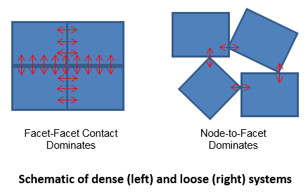
A potential issue with the Node-to-Facet algorithm in dense systems is that it may result in many node-to- node interactions at intersections of blocks. In this case small perturbations in displacement can lead to large changes in the contact stress distribution often resulting in either slow convergence of the stresses or energy gain leading to instability (Penalty based contact algorithms are not conservative when the contact state oscillates between contact and no contact). Consequently, a facet-to-facet approach is sometimes adopted to remove this issue, effectively rounding the corners.
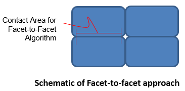
However in ParaGeo an alternative approach for dense systems is adopted, which relies on the incorporation of additional checks in the standard Node-to-Facet algorithm specific to corner point interactions. Therefore a contactor node may be either a sharp corner, defined by the angle between the adjacent facets being greater than a user defined tolerance, or smooth. This condition influences the number of potential targets for the contactor node; i.e.
1A smooth node (internal to a faceted line), is generally restricted to contact with a single target facet.
2A corner contactor node is permitted to contact multiple facets.
The Node-to-Node algorithm in ParaGeo follows the same approach of determining contactors and targets as the Node-to-Facet algorithm but for each node the contact normal direction is calculated as the average of the connected facets normals. This normal direction extends along half of the facet length. This algorithm is suited for small displacement problems (displacement lower than half of the element length) with consistent meshes between contacting surfaces and only one contact interaction per contact surface. In such scenarios this algorithm results in:
1.Smoother/more consistent contact normal direction distribution along a non-flat contact surface.
2.No change in contact directions when a node changes from one facet to another.
3.Consequently smoother results with more contact displacement due to less interlocking.
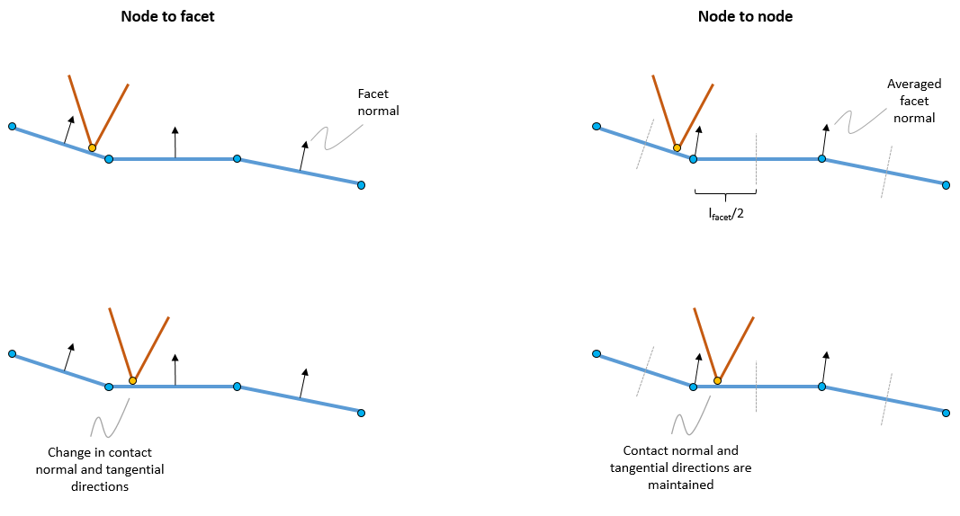
Schematic of update in contact directions for the node-to-facet and node-to-node algorithms
Contact Condition
Contact is established between a contactor node and a target facet when the contactor node penetrates the facet by a small distance. This small mesh penetration distance is named contact normal gap or penetration distance (gn). There is a maximum mesh penetration distance /contact normal gap allowed before there is a loss of contact (which would result in instabilities due to leaking meshes). This distance is named the field distance and is calculated as the product of the target facet length (ltarg) and a user input factor named the field factor (ffield). Note that the adhesion model (tension contact) considers a field distance in the opposite direction of the target facet (a separation field direction).
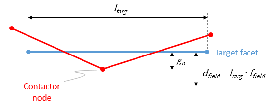
Schematic of field distance
Contact Search
Each node of a contact surface (e.g. a contact surface named CS01 onwards) is considered a potential contactor to any facet from other contact surfaces which are allowed contact interactions with CS01 (e.g. a contact surface named CS02). At the same time every node from CS02 are potential contactors to CS01 facets. In order to establish and solve contact interactions the code needs to identify which contactors are in contact and which facets they are contacting. To that end for every node of CS01 the code checks at each time step whether the node is in contact with any potential facets from CS02 and vice-versa. It should be noted that this operation may be expensive in terms of CPU if we consider potential contacts between all nodes and facets from CS01 and CS02. Also it should be noted that it is expected that not all facets from CS02 will always be near a given node from CS01 and vice-versa and therefore would be unlikely to establish contact in a short term (e.g. in a thrust fault a node near the fault tip in the hanging wall is not expected to establish contact with a facet near the fault root from the footwall). Hence the code internally creates a list with potential target facets for every contact node. The facets that will be included in the contact list for a given node are those which are within a buffer distance (which is a user input). This contact list is updated every global contact search which is performed every N time steps (as input by the user).
Mechanical Contact
The mechanical contact algorithm calculates the reaction forces of two surfaces contacting each other. These reaction forces account for the interaction between the two contacting surfaces preventing mesh penetration and mesh overlap. In the direction normal to the contact surface the normal force depends on the mesh penetration and the normal penalty stiffness. For a given amount of small mesh penetration the larger the stiffness the larger the reaction forces that will prevent further mesh penetration.
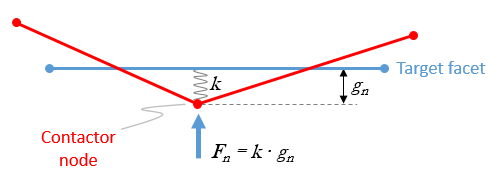
Schematic of normal contact reaction force
Generally it is desired to ensure minimal mesh penetration but it should be noted that the penalty stiffness has an inverse relationship with the contact critical time step such that the higher the stiffness the smaller the contact critical time step and therefore the larger the CPU time to solve a problem (note that the code estimates a critical time step for the contact and a critical time step for the elements and the minimum from the two is used to ensure stability). Thus the choice of the input penalty stiffness value should be based on a balance between ensuring minimal mesh penetration and optimizing the time step size.
Different contact models are defined for the direction normal and tangential to the contact surface respectively. Whereas the normal properties ensure minimal mesh penetration the tangential properties generally control whether or not there will be contact slip. There are a few models available in ParaGeo to model the tangential behaviour such as the Mohr-Coulomb model (with or without cohesion) or a model based on a maximum tangential stress.
In the normal direction, in addition to avoid mesh penetration when the two contact surfaces are in compression, adhesion properties may be defined to avoid separation between the contact surfaces (e.g. in a model subjected to extensional deformation normal faults may tend to separate unless a counter force ensures that the contact surfaces are held together).
It should be noted that contact properties may be defined to not be constant in time or not be homogeneous across a given contact surface. There are several models in ParaGeo which allow defining variation/dependence of contact properties. For example mechanical contact properties may be defined with the following dependencies:
•Depth dependence: Contact properties may be defined as a function of depth. This may be used for example to define an increasing contact stiffness with depth. Thus a high stiffness will be used at larger depths where contact forces may need to sustain thick sedimentation piles and a low stiffness will be used near the top surface where such high stiffness is not required and sediments may be weak and therefore may become unstable if high stiffness is used, i.e. a high reaction force on a weak sediment may result in sediment "bounce".
•Penetration dependence (field dependent): Contact stiffness may be defined to be dependent on the mesh penetration distance / contact normal gap. In this case, a relatively low stiffness may be used when the penetration is low and an increased stiffness defined as the penetration increases. With this method relatively high stiffnesses are only used when required and therefore may help in reducing CPU time (by increasing the contact critical time step) when relatively low stiffness may be used.
•Time dependence: Contact properties may be defined to evolve with time thus facilitating definition of fault property evolution through geological time scales for example.
In addition to the dependent models defined above, it is possible to define contact penalty stiffness as a multiplication factor of the adjacent element stiffness. This allows different stiffnesses at different portions of a fault to be considered which will be consistent with the stiffnesses of the contacting layers. For example, in a fault offset scenario with contact between a shale and a sandstone layer, the multiplication factor contact model may result in different contact stiffnesses on both sides of the fault.
Fluid Flow Contact
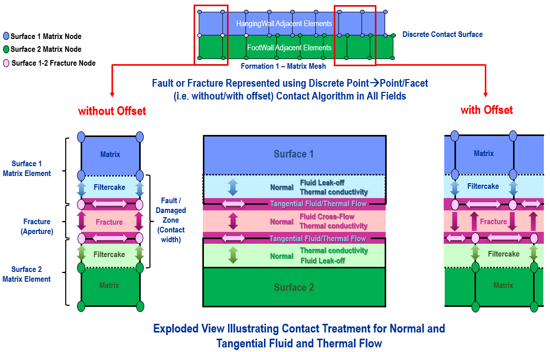
The contact flow algorithm enables the simulation of fluid flow in both normal and tangential directions. In a similar manner to the mechanical contact the properties in the normal and tangential directions are specified independently.
The contact normal flow ensures flow communication between contact surfaces. Also the contact flow algorithm considers two different normal conductivities; the filter cake conductivity which represents the conductivity from the matrix to the fracture and the fracture permeability itself. This enables the pore pressure in the fault to be different from the matrix pore pressure.
The contact tangential flow enables the simulation of flow along faults. The tangential permeability may be defined with a constant value or may be defined as a function of the fault normal stress. In general, fault permeability is expected to decrease as the normal stress on the fault increases (so that a decrease in permeability due to a closing fault gap can be captured).
A contact width representative of the fault width may be defined in order to calculate the storativity of the fault (i.e. the mass of fluid that it can accommodate). In addition to defining the contact width with an input value which may be beneficial for most of the field scale problems where a little bit of mesh penetration is expected, contact width may also be calculated from the actual separation of the contact surfaces on both sides of a fault. This method may be appropriate to model enhanced conductivity during hydraulic fracture or in micro-scale problems where the actual asperity topology in the contact surface is considered.
Thermal Contact
The thermal contact algorithm enables the simulation of thermal heat transfer/flow in both normal and tangential directions. In a similar manner to fluid flow contact, the normal and tangential thermal conductivities and transmissivity (e.g. specific heat capacity) parameters need to be defined.
