Contact_property
Data Structure: Contact_property |
|
Description |
Contact property data structure |
Usage |
Contact_property NUM=ival where ival is the data structure number |
Description |
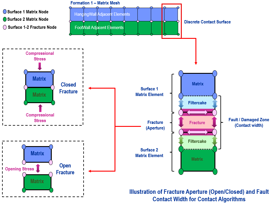
Overview In ParaGeo, contact surfaces are usually used to represent two main classes of structural features; faults (and detachments) and fractures:
Fault •Faults are mode II (shear). •These generally involve a larger damage zone. •Majority of contact simulations are fault-related applications.
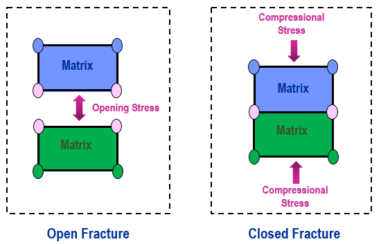
Fracture •Fractures are mode I (tensile). •These are generally too small to be considered in the geometry model and are often modelled in a continuum manner. •Fluid flow in fractures may be represented using the aperture model definitions, e.g. Aperture_model, Aperture_properties, Aperture_property_table. •Fractures are further sub-divided into open or general fractures. •Open fractures are those where there is a clear gap without any contacting points. Typical simulations for open fractures are applications involving injection or shrinkage which result in opening of the contact interface leading to an actual gap in the model. The aperture for open fractures are the actual contact gaps. •General fracture applications are those in which there may be no physical contact gaps in the model but in reality, in the field, gaps do exist due to roughness of the rock surface. Typical simulations with general fractures are applications usually involving compressional stresses on the contact surfaces which results in contact penetration as opposed to contact separation. However when the appropriate conditions are satisfied the contact surfaces may separate and create a gap (e.g. due to an increase in pore pressure and hence a reduction in normal effective stress). In these scenarios the aperture models for general fractures can account for "gaps" that exist in the field and for the consequential hydraulic effects.
The Contact_property data structure is used to specify contact property data (mechanical, porous flow and thermal flow) which is then assigned to geometry surfaces via the Contact_set or the Contact_surface data structures. The contact properties are defined via property models assigned to the normal and tangential direction of the contact surface; i.e.
Mechanical •Compression_model and Compression_properties which define the compressive normal contact model and properties respectively •Tangential_model and Tangential_properties which define the tangential contact model and properties respectively •Adhesion_model and Adhesion_properties which define the tensile normal contact model and properties respectively as well as porous flow and thermal properties for coupled problems, assigned to the normal and tangential direction of the contact surface; i.e.
Porous flow •Flow_model_tangential and Flow_properties_tangential which define the tangential contact flow model and properties respectively •Flow_model_normal and Flow_properties_normal which define the normal contact flow model and properties respectively
Thermal flow •Thermal_model_tangential and Thermal_properties_tangential which define the tangential thermal contact model and properties respectively •Thermal_model_normal and Thermal_properties_normal which define the normal thermal contact model and properties respectively
The variation of contact properties with respect to time and sliding distance can also be specified.
Notes •Several Contact_property sets may be specified. •By default, the contact properties are defined with values dependent on the contact field ( Field_dependent_stiffness_flag = 1). In this case the contact stiffness parameters have units consistent with Young's modulus. |
| Name Name of the contact property set |
Usage |
||||
|
||||
Description |
||||
Name of the contact property set (maximum of 32 characters).
|
| Description Description for contact property data structure |
Usage |
||||
|
||||
Description |
||||
Description for contact property data structure.
|
| Adhesion_model Adhesion model |
Usage |
||||
|
||||
Description |
||||
Valid values are: • 0 - No adhesion • 1 - Elastic (fully bonded) • 2 - Maximum adhesion stress (no debonding) • 3 - Simple debonding model • 4 - Enhanced simple debonding model
|
| Adhesion_rebonding_flag Adhesion model rebonding flag |
Usage |
||||
|
||||
Description |
||||
Valid values are: • 0 - No rebonding after lost contact (default) • 1 - Allow rebonding after lost contact
|
| Adhesion_properties Adhesion model properties |
Usage |
|||||||||||||||
|
|||||||||||||||
Description |
|||||||||||||||
List of adhesion model properties dependent on the model type:
Model 1 - Elastic (fully bonded) This model assumes that debonding only occurs if either the normal gap is greater than the field distance or tangential slip is sufficient for the contactor node to be no longer opposite a target facet. The input values are:
• Location 1 - Adhesion stiffness (penalty) ( Kadh)
Model 2 - Maximum Adhesion Model (fully bonded) This model assumes that debonding only occurs if either the normal gap is greater than the field distance or tangential slip is sufficient for the contactor node to be no longer opposite a target facet. The adhesion stress is however limited to a maximum value. The input values are:
• Location 1 - Adhesion stiffness (penalty) ( Kadh) • Location 2 - Maximum adhesion stress (+ve) ( ASmax)
Model 3 - Simple Debonding Model The simple debonding model assumes that the contact points have an initial bond strength (defined by the initial maximum adhesion stress ASmax0 ), and that if this value is exceeded the bond will be damaged resulting in a reduction in bond strength with continued opening displacement (so that the updated maximum adhesion stress ASmax < ASmax0 ).
The slope of the softening curve is defined by specifying a fracture energy ( Gf) value. Then the Adhesion stifness after softening is defined as Kadhsof =ASmax2*Flen/2*Gf where Flen is the facet length. The expected input values are:
• Location 1 - Adhesion stiffness (penalty) ( Kadh) • Location 2 - Initial maximum adhesion stress (+ve) ( ASmax0) • Location 3 - Fracture energy ( Gf)
Model 4 - Enhanced Simple Debonding Model The enhanced simple debonding model is an enhanced version of the Simple debonding model in which the contact points have an initial bond strength defined by the initial maximum adhesion stress ASmax0. If this value is exceeded the bond will be damaged resulting in a reduction in bond strength with continued opening displacement (so that the updated maximum adhesion stress ASmax < ASmax0 ). The enhaced simple debonding differs with the original simple debonding model (Adhesion model 3) mainly in the softening behaviour: 1 - The softening path in the contact gap vs strength space is linear. 2 - In the original model the strength was assimptotic so never can become zero whereas in this model it does. The expected input values are:
• Location 1 - Adhesion stiffness (penalty) ( Kadh) • Location 2 - Initial maximum adhesion stress (+ve) ( ASmax0) • Location 3 - Fracture energy ( Gf)
|
|||||||||||||||
| Compression_model Compression model |
Usage |
||||
|
||||
Description |
||||
Defines the contact compression model (by number) to be used. Valid values are: • 1 - Linear Elastic
|
| Compression_properties Compression model properties |
Usage |
|||||||||||||||
|
|||||||||||||||
Description |
|||||||||||||||
List of normal compression properties dependent on the model type:
Model 1 - Elastic • Location 1 - Normal Compression Stiffness (Penalty)
|
|||||||||||||||
| Tangential_model Tangential model |
Usage |
||||
|
||||
Description |
||||
Defines the tangential model (by number) to be used in contact. Valid values are: • 1 - Elastic • 2 - Coulomb friction • 3 - Maximum stress • 4 - Mohr Coulomb friction
Notes •The "Elastic" model assumes that all contact points are fully bonded ("tied"). Consequently, when this model is defined, only the tangential stiffness parameter is required to be defined in Tangential_properties.
|
| Tangential_rebonding_flag Tangential model rebonding flag |
Usage |
||||
|
||||
Description |
||||
Valid values are: • 0 - No rebonding after lost contact (model dependent; e.g. cohesion will be zero on a new contact) (default) • 1 - Allow rebonding after lost contact
|
| Tangential_properties Tangential model properties |
Usage |
|||||||||||||||
|
|||||||||||||||
Description |
|||||||||||||||
List of tangential model properties dependent on the model type:
Model 1 - Elastic (no slip) This model assumes that all contact points are fully bonded ("tied") and the input parameters are: • Location 1 - Tangential Stiffness (Penalty) ( Kt)
Model 2 - Coulomb friction model The Coulomb friction model allows frictional slip if: |σt|>μ |σn| where σt the tangential stress, σn is the normal stress and μ is the friction coefficient. The input values are: • Location 1 - Tangential Stiffness (Penalty) ( Kt) • Location 2 - Friction coefficient ( μ)
Model 3 - Maximum stress model The maximum stress model allows frictional slip if: |σt|>σt(max) where σt the tangential stress and σt(max) is the maximum allowable tangential stress. The input values are: • Location 1 - Tangential Stiffness (Penalty) ( Kt) • Location 2 - Maximum stress ( σt(max))
Model 4 - Mohr Coulomb friction model The Mohr Coulomb friction model allows frictional slip if: |σt|>c+μ |σn| where σt the tangential stress, σn is the normal stress, c is the cohesion and μ is the friction coefficient. The input values are: • Location 1 - Tangential Stiffness (Penalty) ( Kt) • Location 2 - Cohesion ( c ) • Location 3 - Friction coefficient ( μ)
|
|||||||||||||||
| Aperture_model Defines the aperture model to be used |
Usage |
||||
|
||||
Description |
||||
In fracture modelling applications, particularly where flow or thermal transfer are considered, it is desirable to specify a fracture width that is dependent on contact state variables. The available aperture models that facilitate this can be divided into two classes of fractures - open and general fractures:
Open Fractures Open fractures are those where there is a clear gap without any contacting points (i.e. contact separation as opposed to penetration). Typical simulations for open fractures are applications involving injection or shrinkage which result in opening of the contact interface leading to an actual gap in the model. The aperture for open fractures are the actual contact gaps. Open fractures can be represented by Aperture_model 5 which is typically used in conjunction with Flow_model_tangential 4, 5 and 8. Note that the aperture in open fractures may also be represented with Aperture_model 3.
General Fractures General fracture applications are those in which there may be no physical contact gaps in the model but in reality, in the field, gaps do exist due to roughness of the rock surface. Typical simulations with general fractures are applications usually involving compressional stresses on the contact surfaces which results in contact penetration as opposed to contact separation. However when the appropriate conditions are satisfied the contact surfaces may separate and create a gap (e.g. due to an increase in pore pressure and hence a reduction in normal effective stress). In these scenarios the aperture models for general fractures can account for "gaps" that exist in the field and for the consequential hydraulic effects. This can be represented by Aperture_model 2 and 3 which are typically used in conjunction with Flow_model_tangential 8 (where tangential permeability is defined as a function of the aperture).
The valid inputs defining one of the available aperture models are: • 2 - (General fractures) Nonlinear aperture model • 3 - (General fractures) Aperture model dependent on contact normal stress (a tabular function specified using Aperture_property_table) • 5 - (Open fractures only) Aperture computed as the actual contact gap
Notes •When Flow_model_tangential is set to 4 or 5 (models using the actual contact gap to calculate the tangential permeability), Aperture_model will automatically be switched to 5 (if defined differently) and the output aperture will be updated accordingly. Any data defining other aperture models will be ignored.
|
| Aperture_properties Aperture properties |
Usage |
|||||||||||||||
|
|||||||||||||||
Description |
|||||||||||||||
The aperture properties are model dependent:
Model 2 - Nonlinear aperture model (General fractures) The fracture stiffness ( Kn) in this model is defined as a function of the initial fracture stiffness ( Kn0) and the initial aperture ( a0) following the function:
The input parameters for this model are: • Location 1 - Initial normal stiffness • Location 2 - Minimum aperture (Optional: Default 1E-6)
The initial aperture is defined by Contact_width.
Model 3 - Aperture dependent on Contact normal stress (General fractures) • Location 1 - Minimum aperture (Optional: Default 1E-6)
A tabular function should be specified using Aperture_property_table
Model 5 - Aperture computed as actual contact gap (Open fractures) • Location 1 - Minimum aperture (Optional: Default 1E-6)
Notes •The minimum aperture definition has no effect on mechanical penetration, it only imposes a minimum aperture for fluid and thermal flow fields.
|
|||||||||||||||
| Aperture_property_table Aperture property table |
Usage |
|||||||||||||||
|
|||||||||||||||
Description |
|||||||||||||||
List of aperture properties dependent on the model type:
Model 3 - Aperture vs stress table (General fractures) • Row 1 - Normal stress (Positive for compression) • Row 2 - Aperture
|
|||||||||||||||
| Shear_aperture_model Defines the shear aperture model to be used |
Usage |
||||
|
||||
Description |
||||
In fracture modelling applications, the shear aperture model allows for the simulation of the dilation effects subject to shear offset (tangential slip). Currently, shear aperture model only works in conjuction with the normal aperture model, thus Aperture_model must also be defined. The available shear aperture models are:
• 1 - Aperture model dependent on absolute shear offset (a tabular function specified using Shear_aperture_property_table) • 2 - Aperture model dependent on relative shear offset (a tabular function specified using Shear_aperture_property_table) • 3 - Dilation formulation at =unettan(ψ)
Note that the total contact aperture will be the sum of the normal component (computed by the Aperture_model defined) and the shear component (computed by the Shear_aperture_model defined).
|
| Shear_aperture_properties Shear aperture properties |
Usage |
|||||||||||||||
|
|||||||||||||||
Description |
|||||||||||||||
The shear aperture properties are model dependent:
Model 1 - Aperture dependent on absolute shear offset (accumulated tangential slip) • Location 1 - Minimum aperture (Optional: Default 0.0)
Model 2 - Aperture dependent on relative shear offset (net tangential slip) • Location 1 - Minimum aperture (Optional: Default 0.0)
Model 3 - Shear_aperture_properties • Location 1 - Dilation angle in degrees • Location 2 - Minimum shear aperture • Location 3 - Maximum shear aperture
Notes •The minimum aperture definition has no effect on mechanical penetration, it only imposes a minimum aperture for fluid and thermal flow fields.
|
|||||||||||||||
| Shear_aperture_property_table Shear aperture property table |
Usage |
|||||||||||||||
|
|||||||||||||||
Description |
|||||||||||||||
Defines the list of shear aperture properties in a tabular form. This is based on the model type being used:
Model 1 - Aperture vs absolute shear offset • Row 1 - Absolute shear offset • Row 2 - Shear aperture contribution
Model 2 - Aperture vs relative shear offset • Row 1 - Relative shear offset • Row 2 - Shear aperture contribution
|
|||||||||||||||
| Flow_model_normal Contact flow model normal to contact surface |
Usage |
||||
|
||||
Description |
||||
Defines the contact flow model normal to the contact surface (by number) to be used. Valid values are: • 1 - Constant fluid conductivity • 2 - Conductivity vs stress table • 3 - Fluid conductivity vs depth table • 6 - Fluid conductivity multiplier relative to the element conductivity adjacent to the contact surface • 11 - Constant intrinsic permeability • 12 - Intrinsic permeability vs stress table • 13 - Intrinsic permeability vs depth table
|
| Flow_properties_normal Contact normal flow properties |
Usage |
|||||||||||||||
|
|||||||||||||||
Description |
|||||||||||||||
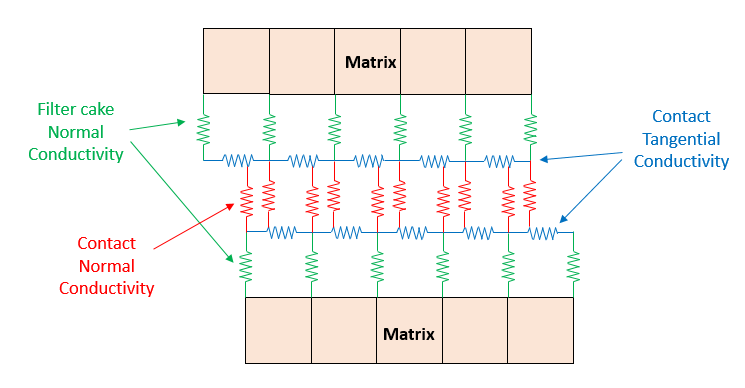
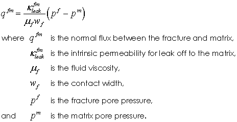
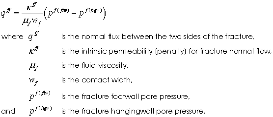
Flow normal to the contact surface is sub-divided into two components: •"Filter Cake Normal Resistance" defining flow from the matrix into the fracture/fault; i.e. between the matrix nodes defining the fault/fracture surface and the corresponding fracture nodes. For fractures this is often associated with the filter cake resistance, whereas for faults it would be the resistance to flow across the fault. •"Contact Normal Conductivity" defining flow across the fracture/fault (internal to the fault), governed by the fault conductivity, between the fracture nodes associated with each face of the fault/fracture.
The fluid conductivity associated with the matrix->fracture flow therefore strongly influences the difference between the fracture/fault and matrix pore pressure, while the contact normal conductivity can be considered a "Penalty" term ensuring approximately equal pore pressure at near neighbour nodes on opposite surfaces of the fault/fracture.
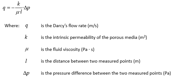
Note that in porous media, flow is governed by Darcy's flow equation:
The normal contact flow properties are dependent on the model type:
Model 1 - Constant fluid conductivity • Location 1 - Contact Normal Fluid conductivity. This represents the fracture permeability • Location 2 - Filter Cake Fluid conductivity. This represents the fault gouge of fracture filter cake permeability
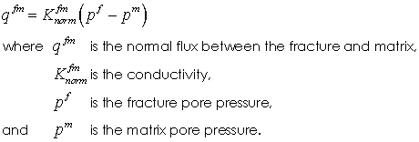
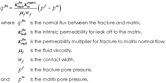
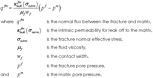
The matrix to fracture flow is governed by the following equation:
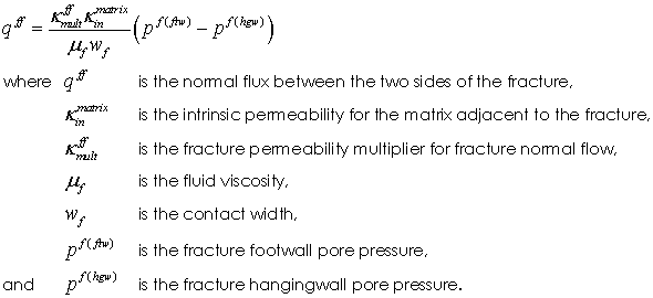
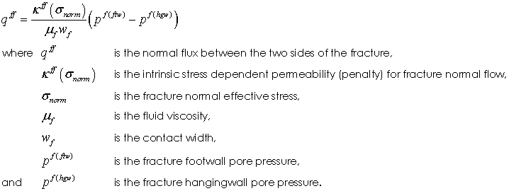
And fracture to fracture flow is governed by the following equation:
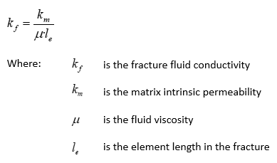
Note that a normal fracture fluid conductivity equivalent to a given matrix permeability may be approximated via the following formula:
Model 6 - Fluid conductivity multiplier This model sets the normal conductivity as a multiplier relative to the element conductivity adjacent to the contact surface. • Location 1 - Contact Normal Fluid conductivity multiplier. This represents the fracture permeability • Location 2 - Filter Cake Fluid conductivity multiplier. This represents the fault gouge of fracture filter cake permeability
The matrix to fracture flow is governed by the following equation:
And fracture to fracture flow is governed by the following equation:
Model 11 - Constant fluid permeabilitty • Location 1 - Contact Normal Penalty (Intrinsic Permeability). • Location 2 - Filter Cake Intrinsic Permeability. This represents the fault gouge of fracture filter cake permeability.
The matrix to fracture flow is governed by the following equation:
And fracture to fracture flow is governed by the following equation:
|
|||||||||||||||
| Flow_normal_table Normal contact flow property table |
Usage |
|||||||||||||||
|
|||||||||||||||
Description |
|||||||||||||||
List of normal contact flow properties dependent on the model type:
Model 2 - Conductivity vs normal stress table • Row 1 - Normal stress (Positive for compression) • Row 2 - Contact Normal Fluid conductivity. This represents the fracture permeability • Row 3 - Filter Cake Fluid conductivity. This represents the fault gouge of fracture filter cake permeability
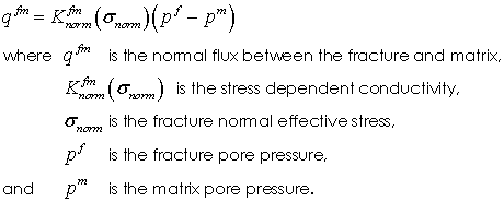
The matrix to fracture flow is governed by the following equation:
And fracture to fracture flow is governed by the following equation:
Model 3 - Conductivity vs depth table • Row 1 - Depth • Row 2 - Contact Normal Fluid conductivity. This represents the fracture permeability • Row 3 - Filter Cake Fluid conductivity. This represents the fault gouge of fracture filter cake permeability
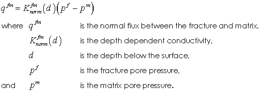
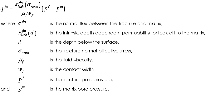
The matrix to fracture flow is governed by the following equation:
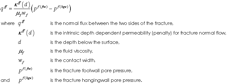
And fracture to fracture flow is governed by the following equation:
Model 12 - Intrinsic Permeability vs normal stress table • Row 1 - Normal stress (Positive for compression) • Row 2 - Contact Normal Penalty (Intrinsic Permeability) • Row 3 - Filter Cake intrinsic permeability. This represents the fault gouge of fracture filter cake permeability
The matrix to fracture flow is governed by the following equation:
And fracture to fracture flow is governed by the following equation:
Model 13 - Intrinsic Permeability vs depth table • Row 1 - Depth • Row 2 - Contact Normal Penalty (Intrinsic Permeability) • Row 3 - Filter Cake intrinsic permeability. This represents the fault gouge of fracture filter cake permeability
The matrix to fracture flow is governed by the following equation:
And fracture to fracture flow is governed by the following equation:
|
|||||||||||||||
| Flow_model_tangential Flow model for flow tangential to contact surface |
Usage |
||||
|
||||
Description |
||||
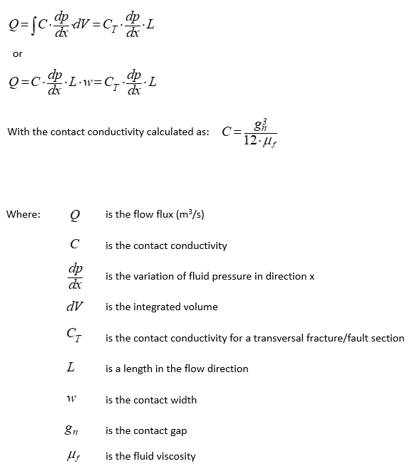
Defines the tangential flow contact model (by number) to be used. Valid values are: • 1 - Constant fluid conductivity (requires definition of Flow_properties_tangential) • 2 - Conductivity vs stress table (requires definition of Flow_tangential_table) • 3 - Conductivity vs depth table (requires definition of Flow_tangential_table) • 4 - Fluid conductivity function of actual contact gap and fluid viscosity ( gn3/12μf) (no properties required) • 5 - Fluid conductivity function of average contact gap and fluid viscosity ( gn(average)3/12μf) (no properties required) • 6 - Fluid conductivity multiplier relative to the element conductivity adjacent to the contact surface (requires definition of Flow_properties_tangential) • 7 - Power law conductivity based on stress (requires definition of Flow_properties_tangential) • 8 - Permeability vs aperture table (requires definition of Flow_tangential_table) • 11 - Constant intrinsic permeabiliity (requires definition of Flow_properties_tangential) • 12 - Intrinsic permeabiliity vs stress table (requires definition of Flow_tangential_table) • 13 - Intrinsic permeabiliity vs depth table (requires definition of Flow_tangential_table)
Notes •Models 4 and 5 are typically associated with the open fracture Aperture_model 5 where the aperture is the actual contact gap and the flow along a fracture can be described as:
Thus, when Flow_model_tangential is set to 4 or 5, Aperture_model will automatically be switched to 5 (if defined differently) and the output aperture will be updated accordingly. Any data defining other aperture models will be ignored.
•Model 8 is typically associated with the general fracture Aperture_model 2 and 3.
|
| Flow_properties_tangential Tangential contact flow properties |
Usage |
|||||||||||||||
|
|||||||||||||||
Description |
|||||||||||||||
List of tangential contact flow properties dependent on the model type:
Model 1 - Constant fluid conductivity • Location 1 - Fluid conductivity
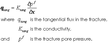
The fracture tangential flow is governed by the following equation:
Model 6 - Fluid conductivity multiplier This model sets the fluid conductivity as a multiplier relative to the element conductivity adjacent to the contact surface. • Location 1 - Contact tangential fluid conductivity multiplier.
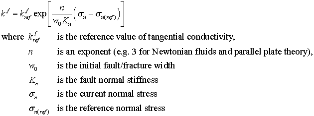
Model 7 - Power law conductivity based on stress
• Location 1 - Reference tangential conductivity ( Kref) • Location 2 - Exponent ( n) • Location 3 - Reference stress ( σn(ref)) • Location 4 - Minimum tangential conductivity ( Kmin) • Location 5 - Maximum tangential conductivity ( Kmax)
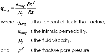
Model 11 - Constant intrinsic permeability • Location 1 - Intrinsic permeability
The fracture tangential flow is governed by the following equation:
|
|||||||||||||||
| Flow_tangential_table Tangential contact flow property table |
Usage |
|||||||||||||||
|
|||||||||||||||
Description |
|||||||||||||||
List of Tangential contact flow properties dependent on the model type:
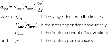
Model 2 - Conductivity vs stress table • Row 1 - Normal stress (Positive for compression) • Row 2 - Fracture fluid conductivity
The fracture tangential flow is governed by the following equation:
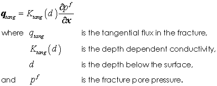
Model 3 - Conductivity vs depth table • Row 1 - Depth • Row 2 - Fracture fluid conductivity
The fracture tangential flow is governed by the following equation:
Model 8 - Intrinsic permeability vs aperture table • Row 1 - Aperture • Row 2 - Intrinsic permeability
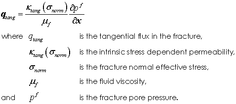
Model 12 - Intrinsic permeability vs stress table • Row 1 - Normal stress (Positive for compression) • Row 2 - Intrinsic permeability
The fracture tangential flow is governed by the following equation:
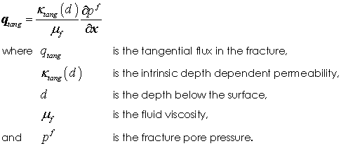
Model 13 - Intrinsic permeability vs depth table • Row 1 - Depth • Row 2 - Intrinsic permeability
The fracture tangential flow is governed by the following equation:
|
|||||||||||||||
| Flow_properties_geostatic Contact normal flow properties for geostatic initialisation |
Usage |
|||||||||||||||
|
|||||||||||||||
Description |
|||||||||||||||
Defines the normal contact flow properties to be used during the geostatic initialization stage. This definition requires Contact_flow_model to be specified as "Constant" in Geostatic_control_data. Then in subsequent stages Contact_flow_model must be set as "Standard" to use the properties defined in Flow_properties_normal. The input parameters for Flow_properties_geostatic are:
•Location 1 - Normal fluid conductivity (Contact). This represents the fracture permeability. •Location 2 - Normal fluid conductivity (Filter cake). This represents the fault gouge permeability. •Location 3 - Tangential fluid conductivity (Penalty).
|
|||||||||||||||
| Thermal_model_normal Thermal model normal to contact surface |
Usage |
||||
|
||||
Description |
||||
Defines the thermal model normal to the contact surface (by number) to be used. Valid values are: • 1 - Constant thermal conductivity • 2 - Conductivity as a function of the normal stress (requires definition of Thermal_normal_table) • 3 - Conductivity as a function of depth (requires definition of Thermal_normal_table) • 4 - Conductivity as a multiplier of fluid conductivity for underlying element • 6 - Conductivity as a multiplier of bulk conductivity for underlying element • 7 - Conductivity as a function of aperture (requires definition of Thermal_normal_table)
|
| Thermal_properties_normal Thermal properties normal to contact surface |
Usage |
|||||||||||||||
|
|||||||||||||||
Description |
|||||||||||||||
List of thermal properties normal to the contact surface dependent on the model type:
Model 1 - Constant thermal conductivity • Location 1 - Thermal normal conductivity (Penalty) • Location 2 - Thermal normal conductivity (Filter cake)
Model 4 - Fluid conductivity multiplier This model sets the normal thermal conductivity as a multiplier relative to the fluid conductivity adjacent to the contact surface. • Location 1 - Contact Normal Fluid conductivity multiplier. This represents the fracture conductivity. • Location 2 - Filter Cake Fluid conductivity multiplier. This represents the fault gouge of fracture filter cake conductivity.
Model 6 - Bulk conductivity multiplier This model sets the normal thermal conductivity as a multiplier relative to the bulk conductivity adjacent to the contact surface. • Location 1 - Contact Normal Bulk conductivity multiplier. This represents the fracture conductivity. • Location 2 - Filter Cake Bulk conductivity multiplier. This represents the fault gouge of fracture filter cake conductivity.
|
|||||||||||||||
| Thermal_normal_table Normal contact thermal property table |
Usage |
|||||||||||||||
|
|||||||||||||||
Description |
|||||||||||||||
List of normal contact thermal properties dependent on the model type:
Model 2 - Conductivity vs stress table • Row 1 - Normal stress • Row 2 - Thermal Penalty conductivity • Row 3 - Thermal Filter Cake conductivity (matrix to fracture)
Model 3 - Conductivity vs depth table • Row 1 - Depth • Row 2 - Thermal Penalty conductivity • Row 3 - Thermal Filter Cake conductivity (matrix to fracture)
Model 7 - Conductivity vs Aperture table • Row 1 - Contact aperture • Row 2 - Thermal Penalty conductivity • Row 3 - Thermal Filter Cake conductivity (matrix to fracture)
|
|||||||||||||||
| Thermal_model_tangential Flow model for thermal flow tangential to contact surface |
Usage |
||||
|
||||
Description |
||||
Defines the tangential thermal contact model (by number) to be used. Valid values are: • 1 - Constant thermal conductivity • 2 - Conductivity vs stress table (requires definition of Thermal_tangential_table) • 3 - Conductivity vs depth table (requires definition of Thermal_tangential_table) • 4 - Conductivity as a multiplier of fluid conductivity for underlying element • 6 - Conductivity as a multiplier of bulk conductivity for underlying element
|
| Thermal_properties_tangential Tangential contact thermal flow properties |
Usage |
|||||||||||||||
|
|||||||||||||||
Description |
|||||||||||||||
List of tangential contact thermal properties dependent on the model type:
Model 1 - Constant thermal conductivity • Location 1 - Thermal conductivity
Model 4 - Fluid conductivity multiplier This model sets the normal thermal conductivity as a multiplier relative to the fluid conductivity adjacent to the contact surface. • Location 1 - Contact tangential fluid conductivity multiplier.
Model 6 - Bulk conductivity multiplier This model sets the normal thermal conductivity as a multiplier relative to the bulk conductivity adjacent to the contact surface. • Location 1 - Contact tangential bulk conductivity multiplier.
|
|||||||||||||||
| Thermal_tangential_table Tangential contact thermal property table# |
Usage |
|||||||||||||||
|
|||||||||||||||
Description |
|||||||||||||||
List of Tangential contact thermal properties dependent on the model type:
Model 2 - Conductivity vs stress table • Row 1 - Normal stress (Positive for compression) • Row 2 - Fracture fluid conductivity
Model 3 - Conductivity vs depth table • Row 1 - Depth • Row 2 - Fracture fluid conductivity
|
|||||||||||||||
| Thermal_properties_geostatic Contact normal thermal properties for geostatic initialisation |
Usage |
|||||||||||||||
|
|||||||||||||||
Description |
|||||||||||||||
Defines the normal contact thermal properties to be used during the geostatic initialization stage. This definition requires Contact_thermal_model to be specified as "Constant" in Geostatic_control_data. Then in subsequent stages Contact_thermal_model must be set as "Standard" to use the properties defined in Thermal_properties_normal. The input parameters for Thermal_properties_geostatic are:
•Location 1 - Normal thermal conductivity
|
|||||||||||||||
| Specific_heat_model Specific heat model for thermal flow tangential to contact surface |
Usage |
||||
|
||||
Description |
||||
Defines the specific heat model (by number) to be used. Valid values are: • 1 - Defined specific heat value for contact • 4 - Specific heat as a multiplier of fluid specific heat for underlying element • 6 - Specific heat as a multiplier of bulk specific heat for underlying element
|
| Specific_heat_properties Specific heat properties for tangential contact thermal flow |
Usage |
|||||||||||||||
|
|||||||||||||||
Description |
|||||||||||||||
List of specific heat properties for tangential contact thermal flow dependent on the model type:
Model 1 - Specified specific heat • Location 1 - Bulk specific heat • Location 2 - Bulk density
Model 4 - Fluid specific heat multiplier This model sets the specific heat as a multiplier relative to the fluid specific heat adjacent to the contact surface. • Location 1 - Fluid specific heat multiplier
Model 6 - Bulk specific heat multiplier This model sets the specific heat as a multiplier relative to the bulk specific heat adjacent to the contact surface. • Location 1 - Bulk specific heat multiplier
|
|||||||||||||||
| Normal_bonding_flag Defines the type of surface separation condition |
Usage |
||||
|
||||
Description |
||||
Defines the type of normal bonding condition. Valid values are: • 0 - Bonding defined by adhesion model only (default). • 1 - Full normal adhesion, which allows tangential sliding but no debonding providing the surface separation distance does not exceed the field. For this case the adhesion model should be set to 1.
|
| Adhesion_dependent_variables Adhesion dependent variables |
Usage |
|||||||||||||||
|
|||||||||||||||
Description |
|||||||||||||||
List of adhesion dependent variables. Allowable variables are: • "Time" - Time • "Depth" - Depth
|
|||||||||||||||
| Adhesion_property_table Adhesion model property table |
Usage |
|||||||||||||||
|
|||||||||||||||
Description |
|||||||||||||||
Adhesion property table defining adhesion properties as a function of the dependent variables. The table data orientation is dependent on the number of dependent variables:
One Dependent Variable •Row 1 - List of dependent variable values •Row 2 - First property value •Row n - Last property value (where n is the number of properties for the adhesion model)
Multiple Dependent Variables Each row of the table must contain the property values, with the number being dependent on the adhesion model, and the associated values of the dependent variables. The number of rows in the table is arbitrary.
Notes •If the number of dependent variables is 1 then the table values must be defined in order starting from the minimum value of the dependent variable to the maximum value of the dependent variable.
|
|||||||||||||||
| Compression_dependent_variables Compression dependent variables |
Usage |
|||||||||||||||
|
|||||||||||||||
Description |
|||||||||||||||
List of compression dependent variables. Allowable variables are: • "Time" - Time • "Depth" - Depth
|
|||||||||||||||
| Compression_property_table Compression model property table |
Usage |
|||||||||||||||
|
|||||||||||||||
Description |
|||||||||||||||
Compression property table defining compression properties as a function of the dependent variables. The table data orientation is dependent on the number of dependent variables:
One Dependent variable •Row 1 - List of dependent variable values •Row 2 - First property value •Row n - Last property value (where n is the number of properties for the compression model)
Multiple Dependent variables Each row of the table must contain the property values, with the number being dependent on the compression model, and the associated values of the dependent variables. The number of rows in the table is arbitrary.
Notes •If the number of dependent variables is 1 then the table values must be defined in order starting from the minimum value of the dependent variable to the maximum value of the dependent variable.
|
|||||||||||||||
| Tangential_dependent_variables Tangential dependent variables |
Usage |
|||||||||||||||
|
|||||||||||||||
Description |
|||||||||||||||
List of tangential dependent variables. Allowable variables are: • "Time" - Time • "Depth" - Depth • "Absolute_slip" - The absolute tangential slip or sliding distance • "Relative_slip" - The relative tangential slip or sliding distance • "Pore" - Pore pressure
|
|||||||||||||||
| Tangential_property_table Tangential model property table |
Usage |
|||||||||||||||
|
|||||||||||||||
Description |
|||||||||||||||
Tangential property table defining tangential properties as a function of the dependent variables. The table data orientation is dependent on the number of dependent variables:
One Dependent Variable •Row 1 - List of dependent variable values •Row 2 - First property value •Row n - Last property value (where n is the number of properties for the tangential model)
Multiple Dependent Variables Each row of the table must contain the property values, with the number being dependent on the tangential model, and the associated values of the dependent variables. The number of rows in the table is arbitrary.
Notes •If the number of dependent variables is 1 then the table values must be defined in order starting from the minimum value of the dependent variable to the maximum value of the dependent variable.
|
|||||||||||||||
| Field_dep_stiffness_model Use field dependent stiffness model |
Usage |
||||
|
||||
Description |
||||
Field dependent stiffnesses allow the initial contact stiffnesses to be reduced, by specifying an initial factor, and to then automatically increase with further penetration. This is useful: •During geostatic initialisation, where initially both the contact forces and the stiffness of the elements adjacent to the contact surfaces are low •In geomechanical applications where steeply dipping contact surfaces may be subjected to small normal contact stress near the surface and high contact stresses at depth.
Valid values are: • 0 - Constant stiffness • 1 - Field dependent stiffness model 1
|
| Field_dep_stiffness_properties Field dependent stiffness properties |
Usage |
|||||||||||||||
|
|||||||||||||||
Description |
|||||||||||||||
Defines the parameters for the field dependent contact stiffness.
Field Dependent Stiffness Model 1 The compression, adhesion and tangential contact stiffness are scaled by the amount of penetration so that the stiffness increases with increasing penetration. The stiffness factor is evaluated by linear interpolation from the lower factor at the lower reference penetration to the upper factor at the upper reference penetration. The actual stiffness factor used is also dependent on the maximum change in contact stiffness between time steps. The input parameters are:
•Location 1 - Lower factor for stiffness (default 0.1) •Location 2 - Upper factor for stiffness (default 2.0) •Location 3 - Lower reference field penetration factor (default 0.0) •Location 4 - Upper reference field penetration factor (default 0.2) •Location 5 - Maximum change factor (default 1.002)
Notes •If Field_dep_stiffness_model is specified but Field_dep_stiffness_properties is not specified then the default values will be used.
|
|||||||||||||||
| Normal_element_stiff_fact Factor of underlying element Young's Modulus to be used as normal stiffness |
Usage |
||||
|
||||
Description |
||||
Factor of underlying element Young's Modulus to be used as normal stiffness. If not specified then the normal stiffness (penalty) will be set using Compression_properties.
|
| Tangential_element_stiff_fact Factor of underlying element Young's Modulus to be used as tangential stiffness |
Usage |
||||
|
||||
Description |
||||
Factor of underlying element Young's Modulus to be used as tangential stiffness. If not specified then the tangential stiffness (penalty) will be set using Tangential_properties.
|
| Adhesion_element_stiff_fact Factor of underlying element Young's Modulus to be used as adhesion stiffness |
Usage |
||||
|
||||
Description |
||||
Factor of underlying element Young's Modulus to be used as adhesion stiffness. If not specified then the adhesion stiffness (penalty) will be set using Adhesion_properties.
|
| Contact_damping_factor Contact damping parameter |
Usage |
||||
|
||||
Description |
||||
Contact damping may be beneficial in both quasi-static and dynamic applications as: •In quasi-static systems the contacting surfaces may oscillate around the steady state solution in the absence of numerical damping. •In dynamic systems contact interaction dissipates no energy in the absence of contact damping, which is contrary to physical observations.
Viscous contact damping can be specified via a Contact_damping_factor ( Ξ) which is the percentage of critical damping specified in the range ( 0.0 ≤ Ξ0 ≤ 1.0 ). The default value is Ξ =0.0 ; i.e. no contact damping.
Notes •Computation of the damping is approximate and if the contact damping factor is too high it may result in energy creation and instability. •The recommended value for contact damping is 0.05.
|
| Contact_width The width associated with contact flow |
Usage |
||||
|
||||
Description |
||||
Contact_width defines the width associated with fluid flow for contact models where the width of the process zone is used to defined the volume of the fracture/fault rather than the contact gap; e.g. flow along closed fractures and faults. Contact_width is used in conjunction with the contact area to define the volume of fluid contained within the fracture. It therefore defines the storativity of the fracture in transient simulations.
Notes •For Aperture_model 2, Contact_width is used to define the initial aperture. •For all aperture models, Contact_width definition only influences flow across the fracture and has no bearing on flow along the fracture.
|

