Contact_set
Data Structure: Contact_set |
|
Description |
Contact set data structure |
Usage |
Contact_set NUM=ival where ival is the data structure number |
Description |
Overview The Contact_set data structure allows a list of geometry sets that are potentially in contact with each other or themselves to be defined with a given set of contact properties. Furthermore it enables the definition of the geometric thresholds used to determine the contact interactions between the nodes and lines of the geometry sets included in the list.
Notes •Several Contact_set sets may be specified. This may be desirable for example when different contact properties are required for different geometry entities.
|
| Name Name of the contact set |
Usage |
||||
|
||||
Description |
||||
Name of the contact set (maximum of 32 characters).
|
| Algorithm Contact algorithm |
Usage |
||||
|
||||
Description |
||||
Defines the contact algorithm to be used in the simulation. Valid values are: • "Penalty" - Penalty method (Default)
|
| Description Description of contact set |
Usage |
||||
|
||||
Description |
||||
Description of contact set (maximum of 128 characters).
|
| Property_name Contact property set name |
Usage |
||||
|
||||
Description |
||||
Specifies the name of the Contact_property data structure defining the contact properties to be assigned to the contact set (maximum of 32 characters).
|
| Property_number Contact property set number |
Usage |
||||
|
||||
Description |
||||
Specifies the number of the Contact_property data structure defining the contact properties to be assigned to the contact set.
|
| Slip_update_model Method for computing fault slip |
Usage |
||||
|
||||
Description |
||||
Method for computing fault slip. Valid options are: • 1 - Standard algorithm (Default) • 2 - Small offset algorithm
|
| Pore_force_no_contact_update Pore force no contact update |
Usage |
||||
|
||||
Description |
||||
Defines whether the pore pressure contribution to contact nodes that are not in contact is updated. Valid values are: • 0 - Do not update pore force if no contact(Default) • 1 - Do update pore force if no contact
|
| Slip_update_frequency Fault slip update frequency |
Usage |
||||
|
||||
Description |
||||
Defines the frequency (specified in number of mechanical time steps) at which fault slip calculation (for output to plot file) is updated. Valid values are: •-1 - At plot output only (Default) • 10 - Every n steps (n>0, e.g. 10)
Notes •In coupled simulations, the specified frequency is still the number of mechanical time steps as opposed to number of flow increments. •In coupled simulations, in addition to fault slip being updated at the frequency defined by Slip_update_frequency or at plot output if Slip_update_frequency is not defined, fault slip is also updated at every coupling step.
|
| Slip_ref_update_frequency Fault slip reference update frequency |
Usage |
||||
|
||||
Description |
||||
Defines the frequency (specified in number of mechanical time steps) at which the reference position for fault slip calculation (for output to plot file) is updated. The initial fault slip reference position is defined at first contact. Valid values are: •-1 - At every fault slip update (Default, see note 2 below) • 0 - At each remesh • 10 - Every n steps (n>0, e.g. 10)
Notes •In coupled simulations, the specified frequency is still the number of mechanical time steps as opposed to number of flow increments. •In coupled simulations, unlike fault slip update, the slip reference position is not automatically updated at every coupling step.
|
| Slip_rate_update_frequency Fault slip rate update frequency |
Usage |
||||
|
||||
Description |
||||
Defines the frequency (specified in number of mechanical time steps) at which fault slip rate calculation (for output to plot file) is updated. Valid values are: •-1 - At plot output only (Default) • 10 - Every n steps (n>0, e.g. 10)
Notes •In coupled simulations, the specified frequency is still the number of mechanical time steps as opposed to number of flow increments.
|
| Geometry_sets List of geometry sets defining the contact set |
Usage |
|||||||||||||||
|
|||||||||||||||
Description |
|||||||||||||||
Defines the list of geometry sets or part geometry sets that define the contact set. Each geometry or part geometry set listed here are considered a Contact_surface. At least one geometry set or part geometry set must be specified unless all geometry is to be used.
|
|||||||||||||||
| Damage_geometry_sets List of pre-damaged geometry sets |
Usage |
|||||||||||||||
|
|||||||||||||||
Description |
|||||||||||||||
When using the aperture model that considers damage Damage_geometry_sets allows to defines a list of geometry sets within the contact set that are considered damaged from the begining of the simulation. Nothe that in 3D such geometry sets must be either Surfaces or Nodal geometry sets.
Notes •Refeer to Damage_init_aperture keyword within Contact_property data structure for more information on the contact aperture model considering damage
|
|||||||||||||||
| Buffer_factor Factor of contact facet length for evaluation of search buffer box size |
Usage |
||||
|
||||
Description |
||||
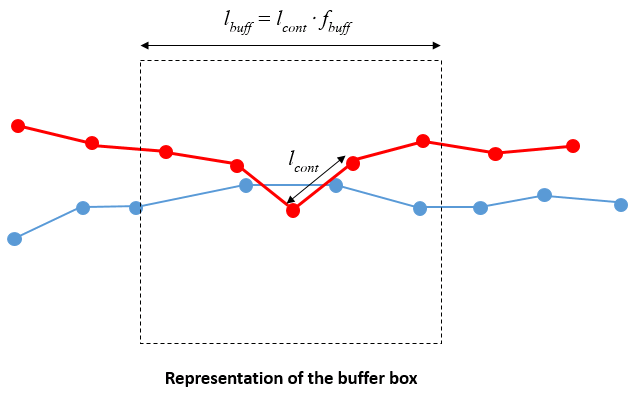
The global contact search algorithm performs an initial search to identify all facets within the zone of the contact point. This zone is defined as the "buffer box". The buffer box is square with a side length ( lbuff) defined as: lbuff = lcont fbuff where lcont is the average length computed from the facets adjacent to the contact point, and fbuff is the buffer factor
Generally with nodal-facet contact fbuff >1 with the default value being 5.0 for 2D and 1.0 for 3D. However, when nodal-nodal contact is used, the buffer factor required is much less and the recommended value for both 2D and 3D is 0.05. Note that nodal-nodal contact is defined in the Contact_global data structure via the Algorithm keyword with value set to 2.
|
| Corner_projection_size Size of corner back projection (for dense systems) |
Usage |
||||
|
||||
Description |
||||
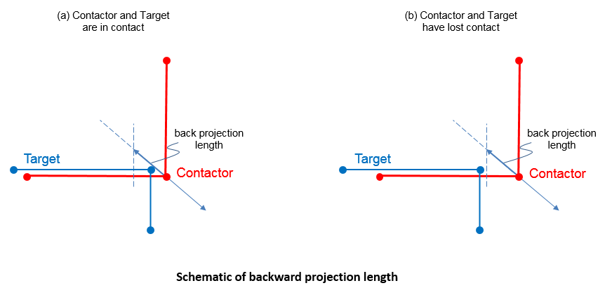
Corner_projection_size defines the length of the back projection of the contact point when assessing whether a point overhanging a convex target corner should remain in contact. Corner_projection_size is specified as a fraction of the target facet length and is generally a small number with the default value being 0.03.
|
| Corner_region_size Size of corner region (for dense systems) |
Usage |
||||
|
||||
Description |
||||
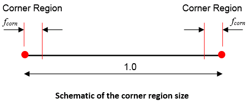
Corner_region_size defines the size of the zone adjacent to the target facet nodes that should be treated as a potential contactor - > facet corner point contact. Corner_region_size is specified as a fraction of the target facet length and the allowable range is 0.0 < Corner_region_size < 0.1, with the default value being 0.02. The default value is generally recommended and larger values should be used with caution.
|
| Corner_angle_tolerance Size of corner angle tolerance (for dense systems) |
Usage |
||||
|
||||
Description |
||||
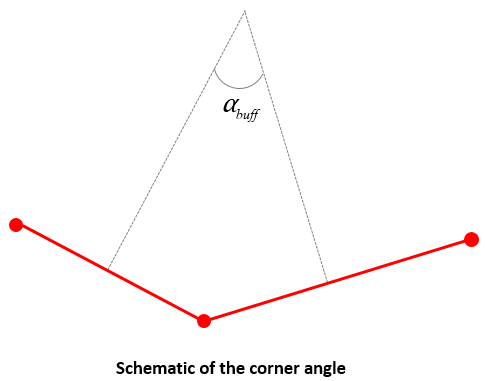
The corner angle tolerance is used to define whether a contact point should be treated as being part of a smooth surface or a sharp corner. The point is treated as a sharp corner if the angle between the facet normal exceeds Corner_angle_tolerance. The default value of the corner angle tolerance is 45 degrees.
|
| Field_factor Factor of contact facet length for evaluation of field (default 0.2) |
Usage |
||||
|
||||
Description |
||||
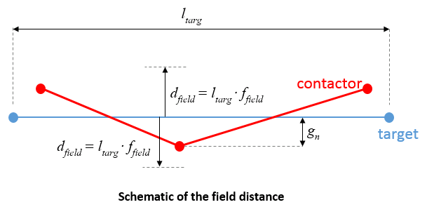
The "Field" is the zone around the target facet that is considered when resolving the contact condition. The field is projected in front of (potentially adhesion) and behind (penetration) the contact facet for a distance known as the "Field Distance". The field distance ( dfield) is defined using the target facet length ( ltarg) and the field factor ( ffield) as:
dfield = ltarg ffield
Notes •Field_factor, together with the target facet length, defines the maximum penetration above which contact is no longer considered. In cases where multiple contact surfaces exist, it also prevents contact when a node is "behind" a target facet but some distance away. The field factor should therefore generally not exceed 0.3.
|
| Normal_dir_chk_angle Max allowable angle between normals to be considered facing each other |
Usage |
||||
|
||||
Description |
||||
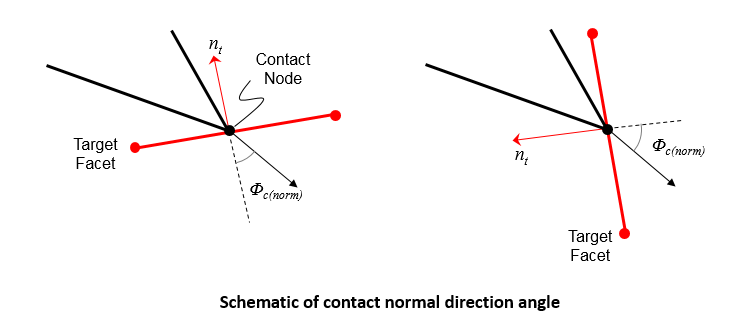
The Normal_dir_chk_angle ( φ(norm)(max)) is used to eliminate potential target facets for a contact point based on the relative normal or the contact point and the target facet. Specifically if the angle between the two normals φ(norm) exceeds φ(norm)(max) then the contact facet will be ignored. The default value of φ(norm)(max) is 80 degrees and smaller values are not recommended.
|
| Trigger_search_velocity Critical velocity which triggers a contact search for a point |
Usage |
||||
|
||||
Description |
||||
Critical velocity which triggers a contact search for a point. This may be useful for loosely packed systems where new contacts are likely. If the value is specified as zero then the critical velocity check is not used. The default value is zero.
|
| Contactor_corner_model Corner contact model type number |
Usage |
||||
|
||||
Description |
||||
Corner contact model type number. Valid values are: • 0 - Loose system, no corner model • 1 - Dense system, contact with the adjacent facets is maintained but contact with additional facets is allowable (DEFAULT) • 2 - Dense system, contact with the adjacent facets is maintained but contact with additional facets is prevented until the overlap exceeds the corner tolerance (effectively rounding the corner)
|
| All_geometry_flag Global geometry flag for usage of external surfaces |
Usage |
||||
|
||||
Description |
||||
Flag indicating whether all external surfaces are used for contact. Valid options are: • 0 - All external surfaces used OFF (DEFAULT if geometry sets are defined) . • 1 - All external surfaces used ON (DEFAULT if no geometry sets are defined). Create one geometry set per surface. • 2 - All external surfaces used ON. Create one geometry set for the whole contact set.
|
| Self_contact_flag Self contact search flag |
Usage |
||||
|
||||
Description |
||||
Self_contact_flag is used to specify whether a contact operation is allowed for a geometry entity with itself or not (e.g the top surface of an overturned thrust). Valid values are: • 0 - Self contact OFF (DEFAULT) • 1 - Self contact ON
|
| Global_update_frequency Frequency for update of global search |
Usage |
||||
|
||||
Description |
||||
Defines the frequency (specified in number of time steps / time increments) for performing a contact global search to update the contact target facets list for each contact node . The target facet list for each contactor node are those facets with which the contactor can establish contact. Those facets are the ones within the buffer box when the global search is performed. The default value is: •Explicit Geomechanical-only analysis: update every 500 steps •Coupled field analysis (incremental): every 10 coupling steps
Notes •For the node-node contact algorithm global contact search is only performed at the start of a stage.
|
| Print_search Search print flag |
Usage |
||||
|
||||
Description |
||||
Flag to indicate whether the contact search is written in the .res file. Valid values are: • 0 - Print search OFF (DEFAULT) • 1 - Print search ON • 2 - Detailed print search ON (>1)
|
| Edge_search_frequency Frequency for edge nodes search |
Usage |
||||
|
||||
Description |
||||
Defines the frequency (in number of time steps) for update of global search of edge nodes. The default value is one tenth of the Global_update_frequency. If input is negative then edge search is switched off, i.e. the search for all contact nodes will only be performed at global search.
|
| Thermal_advection_flag Flag to include thermal convection terms |
Usage |
||||
|
||||
Description |
||||
Defines whether thermal advection is to be considered. Valid values are: • 0 - Do not include advection terms • 1 - Include advection stiffness terms with Petrov Galerkin streamline upwinding (default) • 2 - Include advection terms without Petrov Galerkin streamline upwinding • 3 - Include advection stiffness and storativity terms with Petrov Galerkin streamline upwinding
|
| Memory_optimisation_flag Memory optimisation flag |
Usage |
||||
|
||||
Description |
||||
Defines whether the update for the contact set should be optimised for memory. If set then global search data will be de-allocated after use to save memory. This will lead to increased CPU cost if further global searches are performed as the search data will need to be reformed. Valid values are: • 0 - Do not optimised the memory for global searches (default) • 1 - Optimise the memory for global searches
|
| Four_noded_facet_flag Flag to activate 4 noded facet |
Usage |
||||
|
||||
Description |
||||
Activate the 4-noded facet to be used in the simulation. Valid values are: •-1 - Not assigned, use global value (Default) • 0 - Three noded facet • 1 - Four noded facet
|
| Lumped_storativity_flag Lumped storativity flag |
Usage |
||||
|
||||
Description |
||||
!> Defines whether a consistent or lumped storativity will be used in the porous flow field. Valid values are: • 0 - Consistent storativity matrix (default) 2by2 integration • 1 - Lumped storativity matrix
|
| Contact_storativity_model contact storativity model |
Usage |
||||
|
||||
Description |
||||
Defines the type of contact storativity model. Valid values are: • 1 - 1/K_f (Default) • 2 - 1/K_c + a/K_f
|

