Fracture_data

Contents
Data Structure: Fracture_data |
|
Description |
Fracture data structure |
Usage |
Fracture_data NUM=ival where ival is the data structure number |
Description |
Overview Fractures in ParaGeo may be modelled in a discrete approach via definition of contact surfaces or in a continuum approach (i.e. fractures are contained in finite elements) using Fracture_data. The Fracture_data structure defines all fracture properties directly related to pre-existing or newly created (e.g. hydraulic fracture) fractures for all fields. The data required is dependent on the active fields and on the particular analysis options and fracture models selected for those fields.
Fracture sets are assigned to specific formations in Material_data. All elements in the formations with assigned fracture sets will contain one or multiple fractures (depending on fracture spacing and characteristic element length) for each of the assigned fracture sets. There is an option however to confine fractures to specific regions of formations via definition of fracture location using an active flag for fractures in Spatial_grid data and Spatial_state_set.
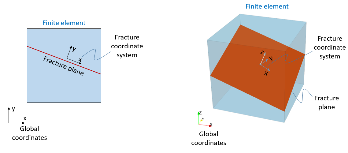
Orientation of a given fracture set is defined via an assigned Coordinate_system with the fracture plane orientation being normal to the vertical components of the assigned coordinate system (i.e. Y axis in 2D problems and Z axis in 3D problems).
Different fracture behaviour for the different fields may be characterized by defining the models of choice: •Fracture type: Defines whether the fractures are pre-existing or propagate according to a defined criterion. •Mechanical model (normal) : Defines the mechanical behaviour of the fracture in the normal direction. This can be fracture with no compliance, fracture with linear elastic behaviour or fracture with non-linear elastic behaviour. •Mechanical model (shear): Defines the mechanical behaviour of the fracture in the fracture plane directions. This may consider no compliance of the fracture in the shear direction, linear elastic behaviour, non-linear elastic behaviour or may consider plasticity via a strength criterion. •Flow model: Defines the flow behaviour of the fracture. Usually permeability multipliers that enhance flow are provided for certain conditions which may be based on stress, strain or aperture.
Bedding Plane Slip Bedding plane slip can be allowed by defining a fracture set parallel to the bedding plane orientation and define a shear slip criterion. In order to achieve that, the following are required: 1) A Coordinate_system with direction cosines defined for horizontal orientation and reference_orientation set as "bedding". This will define the bedding plane orientation at element level. Note that such coordinate system must be assigned within Group_data. 2) Set the reference_orientation to "Material" in the Fracture_data. This will use the bedding plane orientation previously defined at element level as the current fracture set orientation. 3) Definition of a shear strength criterion (e.g. Shear_model_type "MaxShear" will allow bedding plane slip when the shear stress aligned with fracture orientation exceeds the specified value).
Hydraulic Fracture In ParaGeo we can model the development of hydraulic fractures normal to the minimum principal stress usin a continuum approach. Hydraulic fractures increase the permeability and may be considered to become planes of mechanical weakness by defining the appropiate properties. Considering Hydraulic fractures in a simulation requires: •1) Defining Fracture_data and assign the fracture sets to the materials that will be allowed to develop hydraulic fractures •2) Fracture_type (or Propagation_properties) within Fracture_data must be set to HydroFixed (generally used) or HydroRotate •3) Propagation_properties must be defined to set the minimum principal effective stress required to develop an hydraulic fracture. •4) Defining the Conductivity_model to be adopted for the hydrailic fracture
Then in order to consider mechanical weakness along the fracture plane the corresponding keywords need to be defined as well.
Previously developed hydraulic fractures may become closed (and hence stop contributing to an enhanced permeability in the formation) when the minimum principal stress increases above the defined threshold value. The state of the hydraulic fracture may be visualised by plotting the Fracture State variable. This may take the following values: •0 - Hydraulic fracture not developed yet •1 - Open hydraulic fracture •2 - Closed hydraulic fracture
Fracture State should not be confused with the Active Flag values (also visualisable in ParaView) which depending of the value defines: •- 2 - Geostatic initialisation (development of hydraulic fractures is prevented during initialisation stage) •0 - Hydraulic fracture not developed yet (but will develop if conditiors are met) •1 - Hydraulic fracture has developed (although current status may be either open or closed) •2 - Hydraulic fracture switched OFF for the formation (hydraulic fracture will not develop)
In order to switch off the potential development of hydraulic fractures (i.e. assign Active Flag 2) in a given formation the keyword Fracture_activation_flag must be set to 2 in Group_data (pre-existing formations) or/and in Sedimentation_data (for deposited formations).
Note that in order to prevent the potential development of hydraulic fractures during geostatic initialisation the formation must be assigned to a geostatic data set.
Notes •Several Fracture_data data structures may be defined. •If Facies_definition is used with materials that have fractures assigned, all materials must have the same fracture sets ( Fracture_data) assigned.
|
| Name Fracture name |
Usage |
||||
|
||||
Description |
||||
Defines the fracture set name (maximum 32 characters).
|
| Fracture_file Local .mat file name for import (Optional) |
Usage |
||||
|
||||
Description |
||||
Fracture_file allows the import of fracture data from a local .mat file. If the .mat file contains more than one fracture then the Name (if specified) or Mdb_fracture_name will be used to extract the data. The fracture name will be the name specified by Name keyword in the data file (if specified). If the Name keyword is not specified in the data file the Name defined in the .mat file will be used.
Notes •The fracture file name must have extension .mat but may be defined in the data file with or without the extension
|
| Units Units used to define the fracture properties (Optional) |
Usage |
|||||||||||||||
|
|||||||||||||||
Description |
|||||||||||||||
Units used to define the fracture properties. Vector dimensioned 4 where: •Location 1 - units for length e.g. ("m", "mm", "in") •Location 2 - units for stress e.g. ("Mpa", "Kpa", "Pa", "PSI") •Location 3 - units for time e.g. ("s", "hrs", "years", "Ma") •Location 4 - units for temperature e.g. ("Celsius", "Kelvin")
|
|||||||||||||||
| Description Fracture description (Optional) |
Usage |
||||
|
||||
Description |
||||
Description of fracture (maximum of 256 characters)
|
| Fracture_spacing Definition of the length between fractures |
Usage |
||||
|
||||
Description |
||||
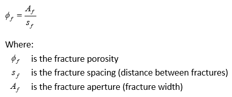
Defines the spacing between fractures in a fracture set. This is used to convert the continuum strain associated with a continuum fracture into an equivalent crack width. It is also used in conjunction to fracture aperture to compute fracture porosity as:
|
| Activation_pore_pressure Pore pressure above which hydraulic fracturing is considered |
Usage |
||||
|
||||
Description |
||||
Defines the pore pressure above which hydraulic fracturing is considered. This optionally allows excluding near surface formations from hydraulic fracturing checks; e.g. during initial deposition where the near surface stresses may be below the hydraulic fracture stress.
|
| Coordinate_system_name Coordinate system name |
Usage |
||||
|
||||
Description |
||||
The Coordinate_system_name keyword is used to assign a coordinate system (by its name) to the fracture set. The fracture plane orientation is set perpendicular to the vertical component of the assigned material coordinate system (i.e. normal to Y coordinate in 2D problems and normal to Z coordinate in 3D problems).
|
| Coordinate_system Coordinate system number |
Usage |
||||
|
||||
Description |
||||
The Coordinate_system keyword is used to assign a coordinate system (by its ID number)to the fracture set. The fracture plane orientation is set perpendicular to the vertical component of the assigned material coordinate system (i.e. normal to Y coordinate in 2D problems and normal to Z coordinate in 3D problems).
|
| Angle Fracture angle in 2-D |
Usage |
||||
|
||||
Description |
||||
The fracture angle (degrees) relative to the reference X-axis; i.e. either the bedding plane or the global X-axis.
|
| Fracture_type Name of fracture propagation model |
Usage |
||||
|
||||
Description |
||||
Defines the fracture model type by name. Valid options are: • "PreExist" - Pre-existing fracture • "HydroFixed" - Simple hydraulic fracture (fixed direction model) • "HydroRotate" - Simple hydraulic fracture (rotating direction model) • "RotateCrack" - Rotating crack model • "Isotropic" - Pre-existing isotropic model with elastic compliance • "P_strain" - Plastic strain isotropic model
Notes •If "HydroFixed", "HydroRotate" or "P_strain" are used then Propagation_properties must be specified.
|
| Propagation_properties Properties for fracture propagation model |
Usage |
|||||||||||||||
|
|||||||||||||||
Description |
|||||||||||||||
Define the properties for establishing fracture propagation conditions. The properties specified are dependent on the Fracture_type model chosen:
Simple Hydraulic Fracture with fixed direction ("HydroFixed") • Location 1 - Minimum principal stress threshold below which fractures would open (compressive is negative). May be considered the fracture tensile strength
Simple Hydraulic Fracture with rotating direction ("HydroRotate") • Location 1 - Minimum principal stress threshold below which fractures would open (compressive is negative). May be considered the fracture tensile strength
Plastic strain isotropic model ("P_strain") • Location 1 - Plastic strain threshold value above which a fracture develops
With this model fractures will be flagged as open if the Plastic strain is greater than the specified values.
Notes •For "HydroFixed" and "HydroRotate" models an additional optional property/condition may be defined in Propagation_properties (and hence IDM =2). This additional property/condition is a percentage of the pore pressure magnitude. If defined a fracture would develop when any one of the two conditions is satisfied, i.e. either the minimum principal stress becomes lower than the specified percentage of the pore pressure or it becomes lower than the specified minimum principal stress threshold value, whichever happens first.
|
|||||||||||||||
| Normal_stiffness_model Name of normal stiffness model for the fracture |
Usage |
||||
|
||||
Description |
||||
Defines the normal stiffness model for the mechanical field of the fracture. Valid options are: • "None" - None (No normal compliance of the fracture; e.g. to define bedding plane slip) • "Elastic" - Constant elastic normal stiffness • "Bandis" - Normal stiffness based on the Bandis Model • "Poroelastic" - Normal stiffness based on the Poroelastic Model • "NormStressAperture" - Normal stress vs aperture model (In tabular form)
Notes •Fracture_spacing must also be specified if "Elastic" or "Bandis" is used.
|
| Normal_stiffness_properties Properties for fracture propagation model |
Usage |
|||||||||||||||
|
|||||||||||||||
Description |
|||||||||||||||
The properties are dependent on the model type: Model 1 "None" No properties required
Model 2 "Elastic" •Location 1 - Normal stiffness
For pre-existing standard fractures the associated fracture state variables are: • F_kn - Normal stiffness • F_dispn - Normal displacement • F_nstrs - Normal stress
For the pre-existing isotropic fractures the associated fracture state variables are: •F_kn - Normal stiffness •F_dporo - Porosity change •F_mstrs - Fracture mean stress
Notes •Fracture_spacing must also be specified
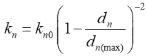
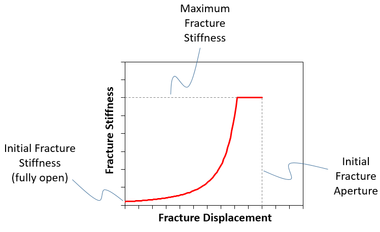
Model 3 "Bandis" This model is based on the Bandis et al. (1983) where the fracture normal stiffness is a function of the normal stress, or equivalently the normal fracture displacement. The model in ParaGeo is defined as a function of the initial fracture stiffness and the maximum normal displacement (Initial Fracture Aperture) according to the following function:
Additionally, a maximum normal stiffness must be defined to prevent the joint stiffness going to infinity if the joint normal displacment approaches the joint maximum normal displacement.
For pre-existing standard fractures the input parameters for this model are: • Location 1 - Initial Normal stiffness • Location 2 - Maximum normal displacement (initial aperture) • Location 3 - Maximum joint stiffness(e.g. the grain stiffness)
The associated fracture state variables are: •F_kn0 - Initial stiffness •F_apert0 - Initial aperture •F_kn - Current normal stiffness •F_dispn - Current normal displacement •F_nstrs - Current normal stress •F_nstfmx - maximum stiffness •F_apert - Current aperture
For the pre-existing isotropic fractures the equivalent model is written in the form
The associated input parameters for this model are: •Location 1 - Initial Normal stiffness ( Kn0) •Location 2 - Initial fracture porosity ( Φf0) •Location 3 - Maximum fracture stiffness (e.g. the grain stiffness)
The associated fracture state variables are: •F_kn0 - Initial stiffness •F_poro0 - Initial porosity •F_kn - Current normal stiffness •F_dporo - Current porosity change •F_poro - Current Porosity •F_mstrs - Current effective mean stress •F_nstfmx - maximum stiffness
Model 4 "Poroelastic" This model is based on an extension of the concepts of poroelasticity to an isotropic fracture. In this model the fracture stiffness is defined in terms of an initial stiffness, the fracture normal stress and a loading modulus kappa via following function:
The fracture stiffness for subsequent unloading is then defined using an additional hysteresis parameter ( fhys ); i.e.
where 0.0 < = fhys < = 1.0 so that
The input parameters for this model are: • Location 1 - Initial Normal stiffness ( Kn0) • Location 2 - Initial porosity ( Φf0) • Location 3 - The compressional modulus ( Κ) • Location 4 - The exponent ( n) • Location 5 - The hysteresis constant ( fhys)
The associated fracture state variables are: •F_kn0 - Initial stiffness •F_poro0 - Initial porosity •F_kappa - Compressional modulus •F_hyster - Hysteresis constant •F_kn - Current normal stiffness •F_dporo - Porosity change •F_poro - Current Porosity •F_mstrs - Current Effective mean stress •F_pormin - Minimum porosity achieved •F_effmax - Maximum effective mean stress achieved
•Fracture_spacing must also be specified •Bandis, S.C. et al. (1983). "Fundamentals of rock joint deformation." International Journal of Rock Mechanics and Mining Sciences & Geomechanics Abstracts 20(6): 249-268.
|
|||||||||||||||
| Normal_stiffness_table Normal stress-based properties |
Usage |
|||||||||||||||
|
|||||||||||||||
Description |
|||||||||||||||
The data is provided as a 2-D table and is model dependent (see Normal_stiffness_model) where a mechanical property (e.g. aperture) is provided as a function of fracture normal stress. Note that the fracture normal stress value within this data structure is positive when in a state of compression. •Row 1 - List of fracture normal stress •Row 2 - E.g. Aperture
|
|||||||||||||||
| Shear_stiffness_model Name of the shear stiffness model for the fracture |
Usage |
||||
|
||||
Description |
||||
Defines the shear stiffness model for the fracture. Valid options are: • "None" - None (no shear compliance of the fracture) • "Elastic" - Constant shear stiffness • "NormFact" - Define shear stiffness as a factor of the normal stifffness
|
| Shear_stiffness_properties Properties for elastic shear model |
Usage |
|||||||||||||||
|
|||||||||||||||
Description |
|||||||||||||||
The properties are dependent on the model type: Model 1 "None" No properties required
Model 2 "Elastic" • Location 1 - Tangential stiffness
The associated fracture state variables are: •F_ks' - Shear Stiffness •F_disps1 - Shear Displacement 11 •F_sstrs1 - Shear Stress 11 •F_sstrs2 - Shear Stress 22 (3-D Only) •F_disps2 - Shear Displacement 22 (3-D Only)
Model 3 "NormFact" • Location 1 - Factor of the normal stiffness (range 0 < factor < 1.0) • Location 2 - Maximum joint stiffness (may differ from the maximum normal joint stiffness)
The associated fracture state variables are: •F_ks' - Shear Stiffness •F_disps1 - Shear Displacement 11 •F_sstrs1 - Shear Stress 11 •F_sstrs2 - Shear Stress 22 (3-D Only) •F_disps2 - Shear Displacement 22 (3-D Only)
|
|||||||||||||||
| Shear_strength_model Name of the shear strength model for the fracture |
Usage |
||||
|
||||
Description |
||||
Defines the shear strength model for the fracture. Valid options are: • "Elastic" - Elastic • "MaxShear" - Maximum shear strength • "MohrCoulomb1" - Mohr Coulomb model (no degradation of strength) • "MohrCoulomb2" - Mohr Coulomb model (linear degradation of strength)
|
| Shear_strength_properties Properties for fracture shear strength |
Usage |
|||||||||||||||
|
|||||||||||||||
Description |
|||||||||||||||
Model 1 "Elastic" No properties required
Model 2 "MaxShear" • Location 1 - Maximum shear stress for fracture or bedding plane
The associated fracture state variables are: •F_sflag - Shear State flag (0 - not slipping, 1 - slipping) •F_syield - Shear Strength (Ft) •F_sstrs - Shear Stress (Resultant) (3-D Only)
Model 3 "Mohr Coulomb1 - No degradation of strength" • Location 1 - Cohesion • Location 2 - Friction angle
The associated fracture state variables are: •F_sflag - Shear State flag (0 - not slipping, 1 - slipping) •F_slip - Shear slip displacement •F_cohes - Shear Cohesion •F_frict - Shear Friction Angle •F_sstrs - Shear Stress (Resultant) (3-D Only)
Model 4 "Mohr Coulomb2 - linear degradation of strength" • Location 1 - Cohesion • Location 2 - Friction angle • Location 3 - Residual Cohesion • Location 4 - Residual Friction angle • Location 5 - Shear displacement when residual values are obtained
The associated fracture state variables are: •F_sflag - Shear State flag (0 - not slipping, 1 - slipping) •F_slip - Shear slip displacement •F_cohes - Shear Cohesion •F_frict - Shear Friction Angle •F_cohesi - Shear Initial Cohesion •F_fricti - Shear Initial Friction Angle •F_sstrs - Shear Stress (Resultant) (3-D Only)
|
|||||||||||||||
| Conductivity_model Name of fracture propagation model |
Usage |
||||
|
||||
Description |
||||
Defines the conductivity model for the fracture by name. Valid options are: • "PermCons" - Permeability values • "PermMult" - Permeability Multiplier • "PermStress" - Permeability Multiplier vs. normal stress • "PermAperture" - Permeability Multiplier vs. Aperture • "PermPorosity" - Permeability Multiplier vs. Fracture Porosity • "FracPermStress" - Fracture Permeability vs. normal stress • "FracPermAperture" - Fracture Permeability vs. Aperture • "FracPermPorosity" - Fracture Permeability vs. Fracture Porosity
|
| Permeability_multiplier Permeability multiplier for fracture |
Usage |
||||
|
||||
Description |
||||
Permeability multiplier for PermMult conductivity model. Permeability of the formation will be multiplied by the specified value while the fracture is open.
|
| Permeability Permeability values for fracture |
Usage |
||||
|
||||
Description |
||||
Permeability value for PermCons conductivity model. Permeability of the formation will be directly replaced by the specified value while the fracture is open.
|
| Conductivity_table Fracture conductivity table |
Usage |
|||||||||||||||
|
|||||||||||||||
Description |
|||||||||||||||
The data is provided as a 2-D table and is model dependent (see Conductivity_model) where a multiplication factor for permeability is provided as a function of Stress/Strain/Aperture: •Row 1 - list of normal Stresses / Strains / Fracture Aperture •Row 2 - Conductivity/Permeability multipliers
|
|||||||||||||||
| Initial_activation_flag Defines whether a fracture is active in the initial state |
Usage |
||||
|
||||
Description |
||||
Flag to define whether a fracture is active in the initial state. Valid values are: • 0 - Inactive • 1 - Active (default)
|
| Isotropic_perm_flag Defines an option applying isotropic permeability |
Usage |
||||
|
||||
Description |
||||
Defines an option applying isotropic permeability for the fracture • 0 - Use coordinate system to assign the permeability for the fracture (default) • 1 - Applying isotropic permeability
|