Ex_006 Eulerian boundaries

This example demonstrates how to use eulerian boundaries to add or remove sediment volume from the system. The eulerian algorithm works as follows:


1.An inflow/outflow sediment velocity is prescribed for the eulerian boundary.

2.The eulerian boundary nodes are moved in / out of the domain according to the prescribed velocity.

3.Then the nodes are pulled back to their original position and the domain is remeshed. This occurs every n time steps as defined by the user.


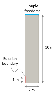
For demonstration of usage of eulerian boundaries a simple column geometry will be used. The column is initially 10 m high and 2 m wide. A 1 m  eulerian boundary is defined in the bottom part of the column's western boundary. The material is modelled using a viscoplastic rheology. Gravity is applied during the first stage of 1 Ma. Then a second stage considering inflow/outflow of sediment during 10 Ma at a specified velocity is performed. Note that quite frequent adaptivity checks are required for eulerian boundaries. Note also that the top surface is constrained with Couple_freedoms to ensure that the vertical displacement is homogeneous as the sediment is added / removed from the domain. Because of the simple geometry and conditions it is straightforward to calculate the expected final column height at the end of the simulation.
 

Ex_006_01

Initial geometry


The data files for the examples are found in: ParaGeo Examples\General Examples\Ex_006\Data


Case1: Inflow of salt

Data File


* Eulerian_boundary    NUM=1

! ---------------------------------

 Geometry_set_name             "Inflow_W"

 Eulerian_update_frequency            100

 Injection_velocity                     1

 Injection_direction              "X_dir"


1.An Eulerian_boundary data structure is defined for the Geometry_set "Inflow_W" which contains the relevant line in the western boundary.

2.The Eulerian_update_frequency is set to 100 so every 100 mechanical time steps the nodes from the eulerian boundary will be returned back to their original position.

3.The Injection_velocity is set to 1 (m/Ma as defined by the problem units). Note that the velocity of injection may be controlled by an assigned time curve by adding the keyword Time_curve n, where n is the time curve number.

4.The Injection_direction is set to "X_dir" so that the eulerian boundary nodes will be moved at a velocity of 1 m/Ma in the X direction.


Case2: Outflow of salt

Data File


* Eulerian_boundary    NUM=1

! ---------------------------------

 Geometry_set_name             "Inflow_W"

 Eulerian_update_frequency            100

 Injection_velocity                  -0.5

 Injection_direction              "X_dir"


1.The data is identical to the previous case with exception to Injection_velocity which is set to -0.5 m/Ma, so that the eulerian boundary nodes will be moved at a velocity of 0.5 m/Ma in X direction in the negative sense (hence leading to salt outflow).

2.Note that the sign of the velocity indicates the sense of displacement in the global coordinate system. Hence a negative velocity injection value  in an eastern boundary would result in volume inflow (see results for Ex_006_Case2b, in which the eulerian boundary is located in the bottom eastern boundary of the column).


Case3: Free eulerian boundaries

Data File


* Eulerian_boundary    NUM=1

! ---------------------------------

 Geometry_set_name             "Inflow_W"

 Eulerian_update_frequency            100

 Eulerian_boundary_type                 0

 Injection_direction              "X_dir"


* Eulerian_boundary    NUM=2

! ---------------------------------

 Geometry_set_name             "Inflow_E"

 Eulerian_update_frequency            100

 Eulerian_boundary_type                 0

 Injection_direction              "X_dir"


1.In this case there are two eulerian boundaries located at the bottom part of the western and eastern column boundaries respectively.

2.Eulerian_boundary_type is set as 0 so that the eulerian boundaries are free eulerian boundaries (inflow/outflow velocity is not prescribed). This means that the material is allowed to enter/leave the domain across this boundary as a result of other boundary conditions and the internal domain deformation / displacements.

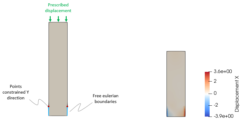
3.In the present case a prescribed compressive displacement is applied at the top of the column and the material is allowed to escape through the two eulerian boundaries.

4.Note that for this case the points at the top of the eulerian boundaries are fixed in the Y direction in order to avoid closure of the eulerian boundaries due to compaction.


Results

The result files for the project are in directory: ParaGeo Examples\General Examples\Ex_006\Results.


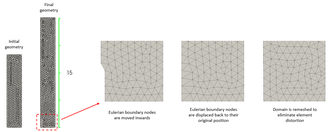
For the present example it is straightforward to calculate the expected final column height. In case 1 the injection velocity was prescribed to 1 m/Ma and inflow occurred during 10 Ma. The eulerian boundary is 1 m high and the column width is 2 m. Hence the expected increase in height can be calculated as Δh = 1 m/Ma · 10 Ma · 1 m / 2 m = 5 m. In the figure below it can be seen that the final column height is approximately 15 m so it has increased 5 m as expected.


In the figure it is also shown the sequence combining the eulerian boundary algorithm with remesh used to simulate salt injection. It should be noted that the additional volume is introduced in the system when the nodes are pulled back to their original position.


Ex_006_02

Results for Case 1 (prescribed salt inflow) with detailed sequence of eulerian boundary and remesh update


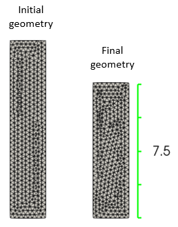
In case 2 the injection velocity was set to -0.5 m/Ma in order to simulate salt outflow from the domain. A decrease of 2.5 m in column height is expected and as can be seen in the figure below the results match that height increment.


Ex_006_03

Results for case 2 (prescribed salt outflow)


In case 3 two free eulerian boundaries at the bottom of both sides of the column are considered. A prescribed downward displacement of 3 m is applied to the top surface. The upper points of the eulerian boundaries are constrained in the Y direction in order to avoid closure of the eulerian boundary as salt is evacuated and the downward displacement progresses. In the horizontal displacement results it can be seen that the free eulerian boundaries allowed for salt evacuation as the salt was subjected to vertical compression.


Ex_006_05

Schematic of boundary conditions (left) and horizontal displacement results (right)


Note that volume inflow/outflow from the domain is monitored in the .res file. For case 3 for example it can be seen that from an initial volume of 20 m3 due to a vertical downward displacement of 3 m the column has lost 6 m3 and is 14 m3 at the end. It can be seen that every eulerian boundary has evacuated almost 3 m3 of salt.


.res file

Data File


Eulerian Boundary Update: Time:     11.000     Boundary:    1 Tot.Vol:   -2.92    


Eulerian Boundary Update: Time:     11.000     Boundary:    2 Tot.Vol:   -2.94    


Outputting Plot File.  Step:      12775 Time:     11.0000    


Model Volume Data.   Time:    11.0000    

============================================================

Group No. Name                              Volume

-------------------------------------------------------

      1 Salt                                14.0309    

-------------------------------------------------------

Total Volume:    14.0309