Notes on Fracture Workflow

Contents
Representation of Fractures in ParaGeo
In ParaGeo fractures may be represented either:
a.In a discrete manner, explicitly represented in the mesh as geometry surfaces and modelled via contact.
b.In a continuum manner, using the embedded fracture approach where properties for the fractures are considered at element level and the macroscopic response relative to the "intact" matrix properties are represented.
In both approaches different models for mechanical, fluid flow and thermal fields are available to represent the behaviour of the fractures. The optimal choice of approach to be adopted for a given application is usually dependent on the application requirements, the relative size of the fracture and the domain and the complexity of the fracture system, i.e.:
▪Size of the fractures relative to the model domain and mesh size: If the fracture size is small relative to the scale of the model geometry and is also small relative to the mesh size, then embedded fracture is the recommended approach. In such scenarios, representation of discrete fractures would be of limited value and would require a large number of element count to achieve a fine mesh discretization around the fractures which may be sub-optimal for the model performance.
▪Complexity of the fracture system: If the application considers a relatively large number of fractures then the embedded fracture approach (continuum) is generally recommended to optimize CPU time and ease modelling tasks. This also facilitates modelling and meshing tasks when there are different number of fractures sets with multiple fractures at different orientations for which discrete representation would result in a large number of complex intersections. Usually, for cases with the order of ~40 fractures the embedded fracture is often preferred.
▪Expected shear/tangential displacement at the fracture: If the target application aims to capture a relatively large tangential fracture displacement (e.g. of the order of an element size) and/or capture a strong displacement gradient near the fracture, representation via the discrete approach (i.e. with contact surfaces) may be required. Nonetheless it should be noted that there is a limit in the displacement that can be accommodated for in the fracture before the fracture geometry becomes distorted and this usually results in large stress concentration at the fracture tips.
Hence the need of using the contact approach is often linked to displacement and meshing considerations or if detailed results at the fracture surface are required. It is noted that both approaches may be used simultaneously; e.g. large scale features may be represented via discrete contact surfaces whereas smaller features within the same model may be represented via the embedded fracture approach.
It is also noted that the embedded fracture framework allows for representation of spatial distribution of properties, which includes the ability to consider the existence of fractures only in selected regions within the model.
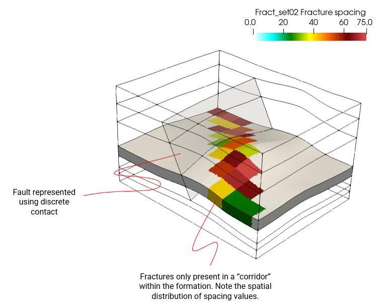
Example of a case (MEM_001 Case06) which combines discrete contact features with the embedded fracture approach. Note that fractures are only activated through a corridor within the model and that spatial distribution of properties has been assigned to those fractures.
Notes on the import of fractures
ParaGeo encompasses functionality to imported fracture systems defined in FracMan data format (.fab files). This includes some basic processing operations which allow transformations to be performed on the original fracture system defined in the imported FracMan file; e.g. scaling the size of fractures, performing an offset or excluding some of the fractures. The processed fracture system may then be exported into a new FracMan file.
When importing FracMan fractures we can initially visualize the location of the imported fractures (which may be as originally defined or processed with defined geometric transformations) relative to the model domain before performing any simulation. It should be noted that one limitation is that an imported fracture set must be contained within a single volume of the model domain and should not intersect any boundary. The user has the option to define a geometric region so that only the fractures fully contained within such region will be considered for import. Hence this facilitates the exclusion of fractures that would otherwise intersect the volume boundary.
The imported fractures may be modelled as discrete meshed surfaces within the model (for which a new mesh will be generated including a split operation to generate the hanging wall and footwall counterparts) or may be used to find the elements of the model mesh that are intersected by the fracture topology and activate embedded fractures only in those elements.
The fractures defined in the FracMan file may be either planar or non-planar. When importing the fractures as discrete surfaces (explicitly represented in the mesh) the following considerations must be taken into account:
▪Planar fractures may intersect each other. In such scenario the intersection topology does not need to be explicitly pre-defined. ParaGeo will automatically calculate the intersection and the appropriate geometry and mesh will be generated accordingly.
▪Non-planar fractures may intersect each other but the fracture topology needs to be specified via facets with intersection topologies explicitly pre-defined in the FracMan file.
Note that the meshed geometry incorporating the discrete fracture network (DFN) may be exported into a .geo file for usage in subsequent simulations.
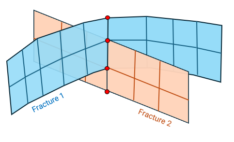
Schematic of definition of non-planar fractures via facets