Geol_001 Geological Modelling Workflow
Note: The present tutorial example is only recommended to advanced users already familiar with ParaGeo.
In the present tutorial example a geological modelling workflow available in ParaGeo will be demonstrated. In this case the workflow encompasses the following four parts:
1.Part 1 - Geometry definition in .dxf format and conversion to a suitable .geo file
2.Part 2 - Geomechanical restoration of the defined 2D geological structure
3.Part 3 - Conversion of restoration results to input data for the forward simulation
4.Part 4 - Forward simulation
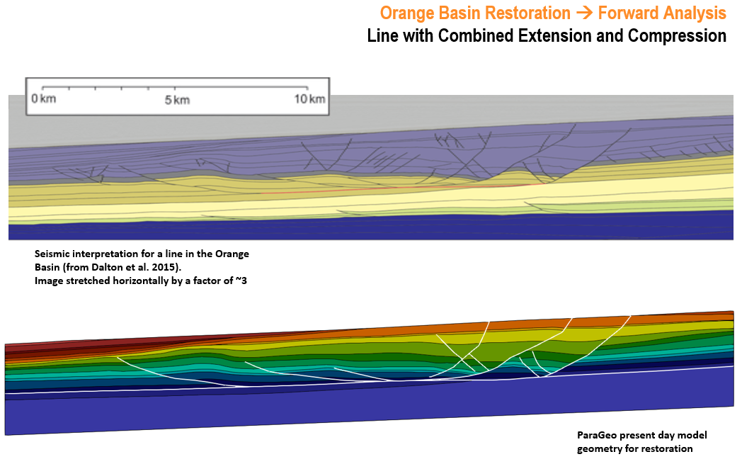
The considered structures for this example are obtained from a published seismic section in the Orange basin. Particularly the Line 2 from Dalton et al. (2015) paper. For this tutorial the focus will be the two thrust faults further to the west. Note that in the publication the vertical exaggeration (V.E.) of the section was c.a. 3 so for the present case the image is stretched accordingly to obtain a V.E. = 1 (i.e. homogeneous scaling is assumed).

Seismic interpretation for Line 2 in the Orange Basin (Dalton et al. 2015). Image stretched horizontally by a factor of c.a. 3 for a V.E. = 1
References
Dalton, T. J. S., Paton, D. A., Needham, T. and Hodgson, N. (2015). Temporal and spatial evolution of deepwater fold thrustbelts: Implications for quantifying strain imbalance. Interpretation, Vol. 3 No.4: 59 - 70.
|
Results of Full Geological Restoration to Forward Simulation Example Undertaken by TCGA (Reference only)
The following shows some results from ongoing work undertaken by TCGA for the full geological restoration to forward simulation model for line 2 in the Orange Basin comprising combined extensional and compressional features. This ongoing work applies the workflow methodology described in this manual (on the smaller simplified model) and shows the capability of the ParaGeo code in undertaking restoration and forward modelling for such complex structures. The results for the full geological model are shown for reference only.
The compression downdip the seismic line is inferred to result as a consequence of the extension updip. However, Dalton et al. have performed several restorations on different seismic lines in the Orange Basin and they consistently found imbalance between the extensional and compressional strain recovered. For the particular section shown below, they found 5.6 % of missing strain which they explain may be lost as horizontal compaction.
Representative ParaGeo model for Line 2 in the Orange Basin (Dalton et al. 2015) with combined extensional and compressional features
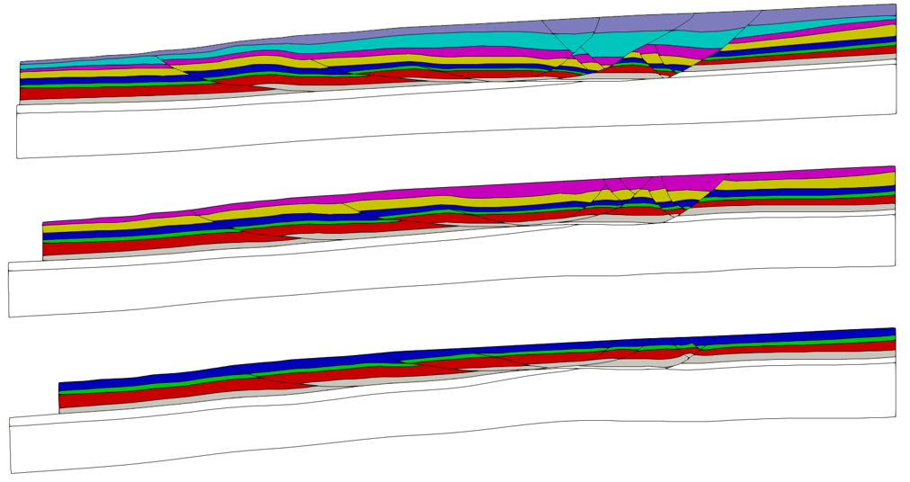
The following images show the geometries at the end of three different restoration stages. The restoration process is performed up to the back-stripping of the top of the pre-kinematic sequence.
Restoration: Geometries at three different restoration steps
During the restoration process, although extensional fault displacement is recovered, there are still substantial amount of non-recovered compressional fault displacements at the locations indicated in the image below. Potential reasons for this could be: •Imprecision / uncertainty in seismic interpretation with shallow fault angles which may result in relatively large error in fault offset at present day. •Effect of assuming a homogeneous velocity for depth conversion. •Non-recovered ductile tectonic compaction (mainly on the upper less consolidated layers).
Restoration: Locations of un-recovered compressional fault displacements
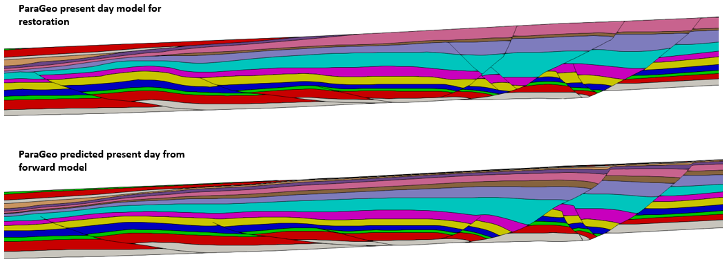
Comparison of the present day geometry defined for the restoration model and the predicted geometry by the forward model simulation (shown below) is remarkably similar although there are some differences which could be improved in additional simulations. Some of these differences could be due to: •Extensional faults that are intersecting have not been propagated during the forward simulation as the interpreted structures are difficult to resolve in restoration and would lead to issues in the forward model. •Fault offset in the compressional region is underestimated as tectonic compaction was not considered in the restoration. •Some of the layer thicknesses are not consistent due to an apparent larger predicted offset in the extensional region and also the decompaction in restoration and compaction in forward model are not 100% consistent. An enhancement in the ParaGeo code to correct for the latter will be implemented. •The fold above the main compressional fault is predicted more gentle than is observed. This could be because extra tectonic compaction is required in the forward model and / or could be an indication that the friction of the fault may have increased with time, thus accumulating the extra shortening as folding rather than by slipping on the faults.
Forward Model: Comparison of present day defined geometry for restoration vs predicted geometry by forward model simulation
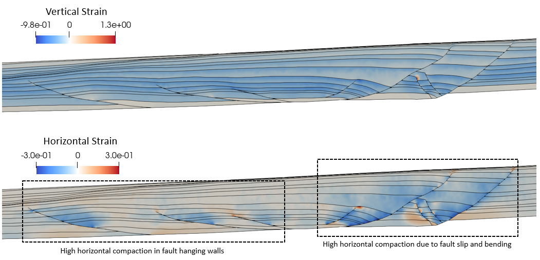
The following images show the horizontal and vertical strain distributions for the predicted forward model. These strain distributions could be used to improve restoration assumptions. High horizontal compression is predicted at the fault hanging walls and in the extensional faults due to fault slip and bending.
Forward Model: Horizontal and vertical strains for the generated forward model
|


