Step06 Forward Simulation
Note that no special / different data other than that discussed in Geol_002 is required for the forward simulation in the present case as the additional features are focussed on assuming different constraints for the restoration. Such restoration constraints will yield different restoration results and hence different displacements in the output grids for the base and the boundaries (which will be used as boundary conditions for the forward simulation). Hence the forward simulation data will not be discussed in detail here.
The data files for forward simulation are provided in Geol_002b\Case01\06_Forward_Sim\Data. Those files are:
1.Geol_002b_Case01_fsim.dat main datafile for the forward simulation.
2.Geol_002b_Case01_rest_formation01.geo initial geometry (last geometry file obtained from restoration)
3.Geol_002b_Case01_RestSurf01.dat file with the restoration surface (defining the sedimentation surface in the forward simulation)
4.Geol_002b_Ss_Si_Sh_Ca.mat file containing the material data for the forward simulation
5.Geol_002b_Case01_fsim_sides.dat datafile containing the geometry sets for the side boundaries
6.Geol_002b_Case01_rest_Disp_formationNN.spat files containing the spatial grids (output from restoration) with the boundary displacements for all stages where NN is the formation number being deposited for that stage.
Results
The results for the present workflow steps are provided in Geol_002b\Case01\06_Forward_Sim\Results. Note that only a selection of the results is provided.
The forward simulation was completed in 24 min using a single processor (3.6 GHz clock speed).
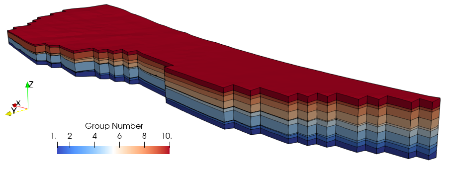
Final geometry after the forward simulation
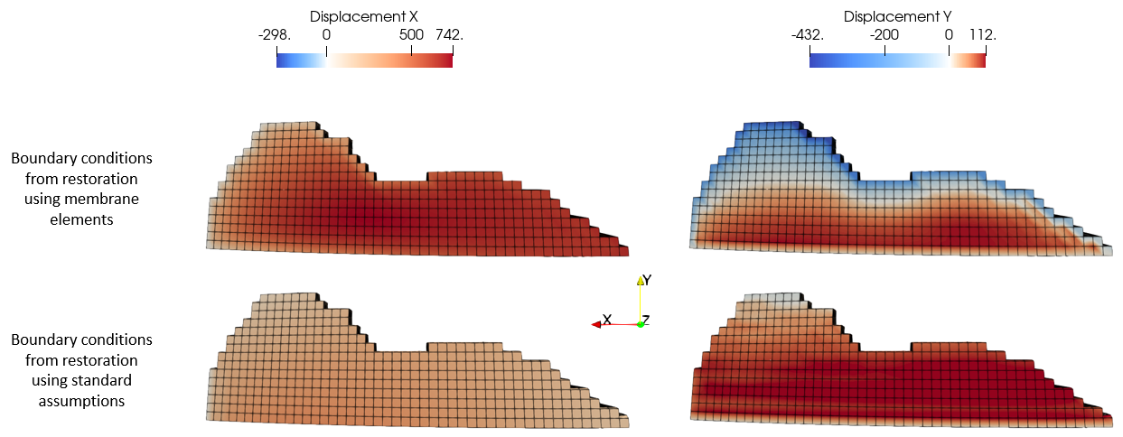
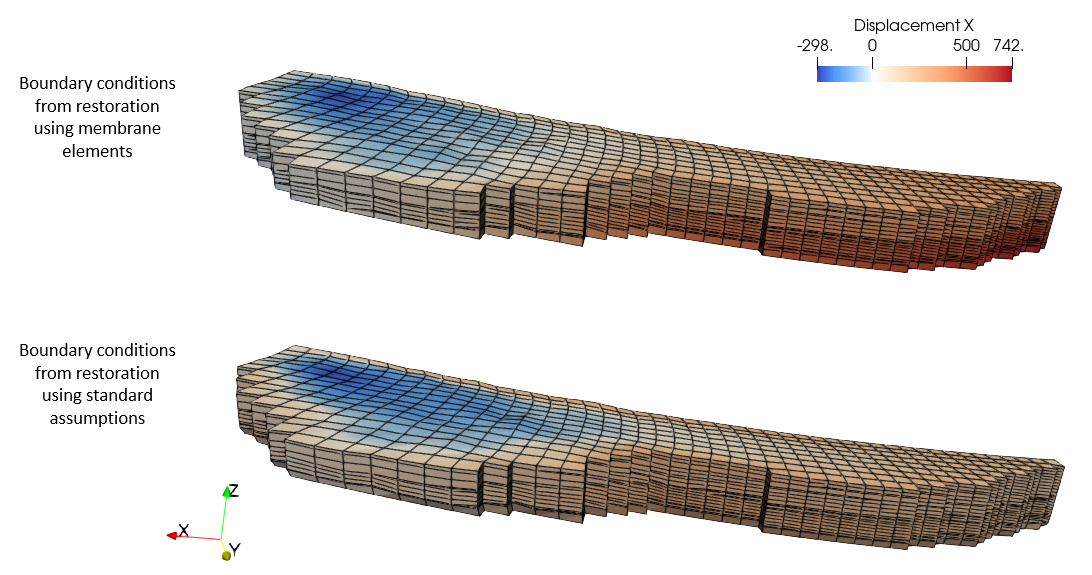
Comparison of the displacement contours for the present case with a case using boundary conditions derived from a restoration with standard assumptions (no membrane elements) is shown below. As expected the present case has larger compression in both, X and Y directions as the membrane elements resulted in larger recovered lengths compared to the case with standard assumptions. The negative displacements in the X direction are found in the eastern flank near the top surface and are attributed to gravity driven displacement following the model slope. This is also observed in the case constrained by boundary conditions derived from restoration with standard assumptions.
Comparison of displacement contours at the base of the model for the present case with a case using boundary conditions from a restoration with standard assumptions (no membrane elements)
View of the displacement in X direction for the present case compared to the case using boundary conditions from restoration with standard assumptions (no membrane elements)
|


