Gmsh_001_Example1: Unstructured Mesh
Introduction
The goal here is to demonstrate the procedure of generating unstructured mesh in cube geometry model using Gmsh.
The learning objectives include
•Creating geometry using Elementary Entities
•Defining control parameter within Gmsh scripts
•Generating unstructured tetrahedral mesh
Demonstration
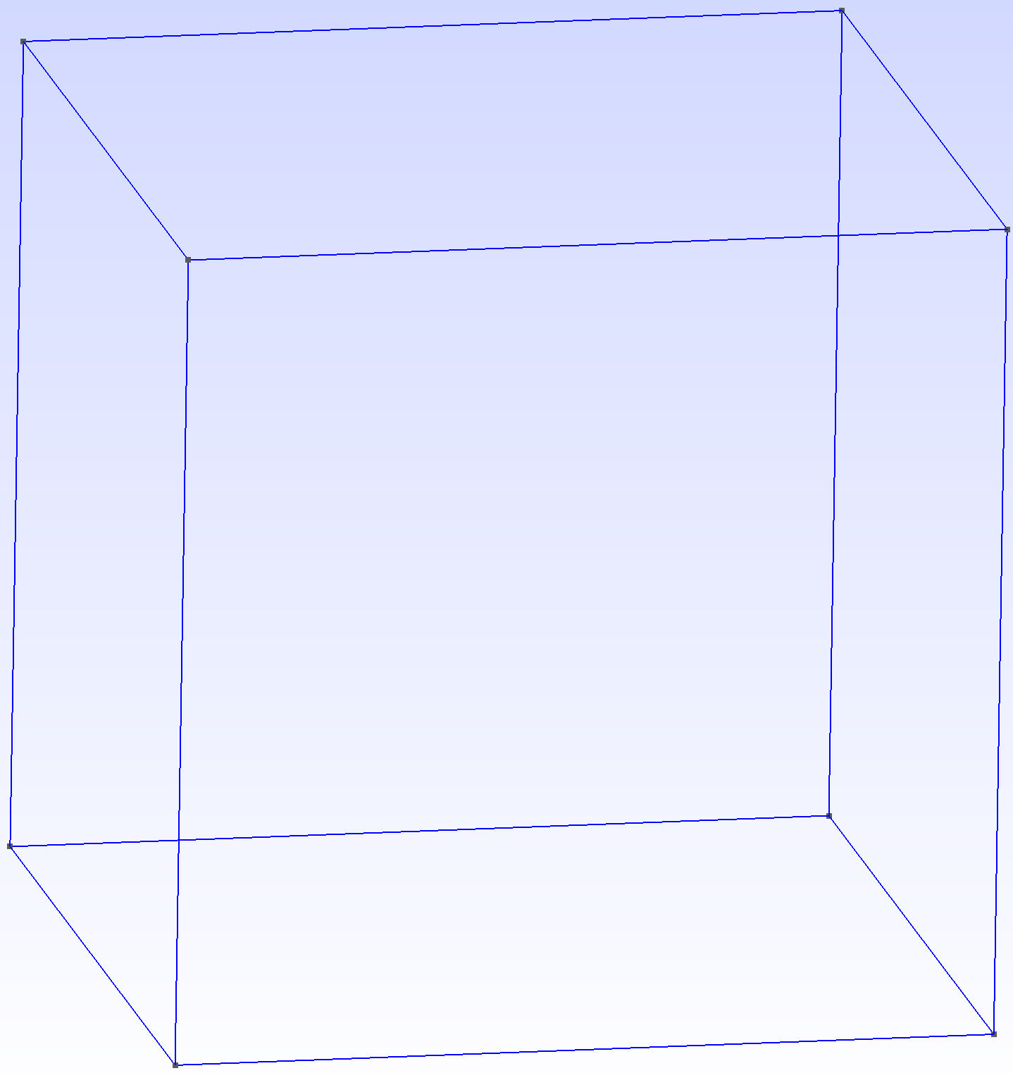
In this example, we are going to create a cube with all sides being 1m in length. We need to first open a new file and save it in a working directory:
1Select "Use '.geo' extension"
2Select OpenCASCADE
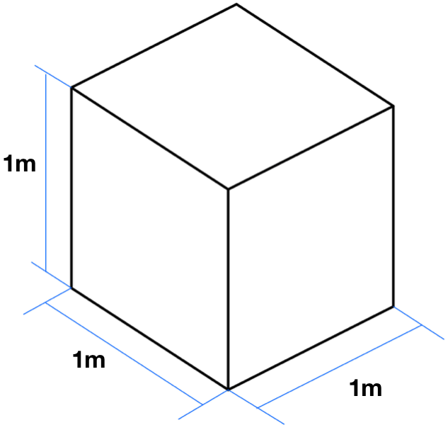
Procedures of creating geometry and unstructured mesh for this model are demonstrated in the following:
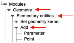
1In Gmsh, we expand Geometry -> Elementary entities -> Add
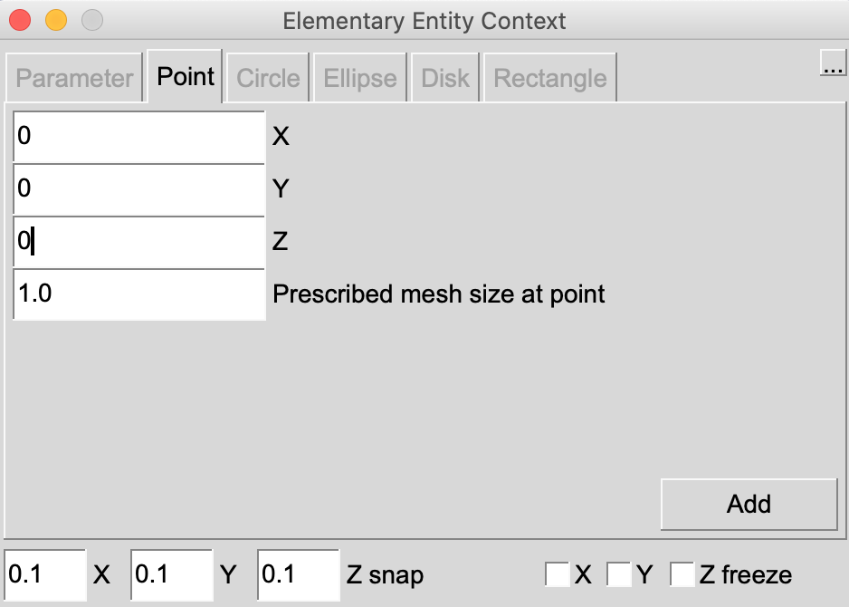
2Under Add category, select Point. This allows us to input the coordinates of vertices.
aIn this example, the points are given as follows
bAfter inputting the coordinates, simply select Add to register the entry. Alternatively, we may click on the geometry interface, and press e to register the entry. 3Close the window and press q to abort. We have now finished defining the points.
|
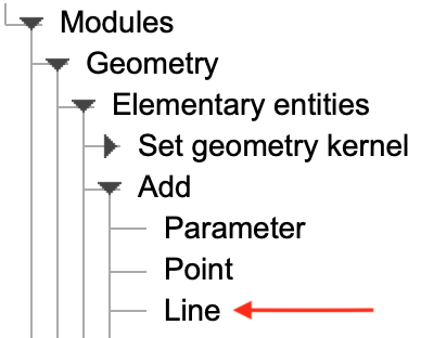
1On the left panel, select Line to connect the points.
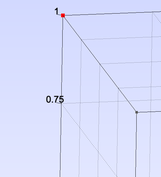
2Now, to define each line, select the start and end points. For each point that is selected, it is highlighted in red.
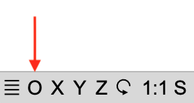
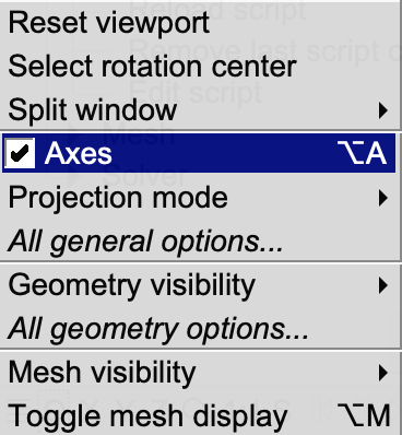
3If the axis lines are obstructing the visibility during point selection, we may turn it off by following these procedures. a.On the bottom left panel, select the O symbol.
b.Uncheck Axes
4After defining all the lines, press q to abort. We have now finished defining the lines.
|
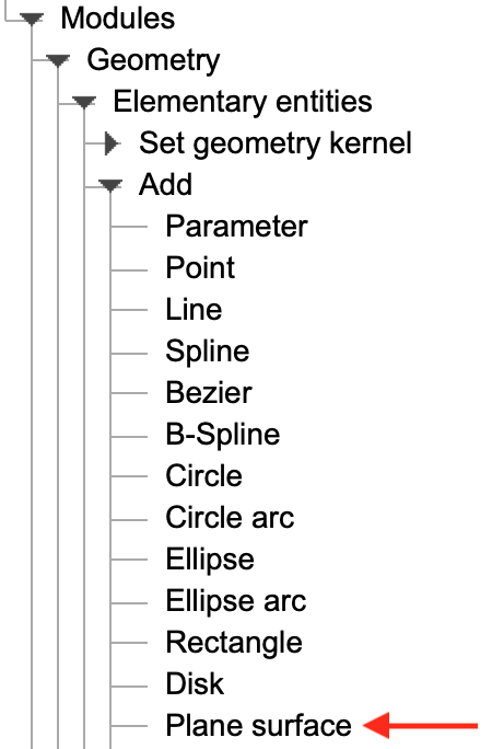
1On the left panel, select Plane surface in order to define each surface of the geometry.
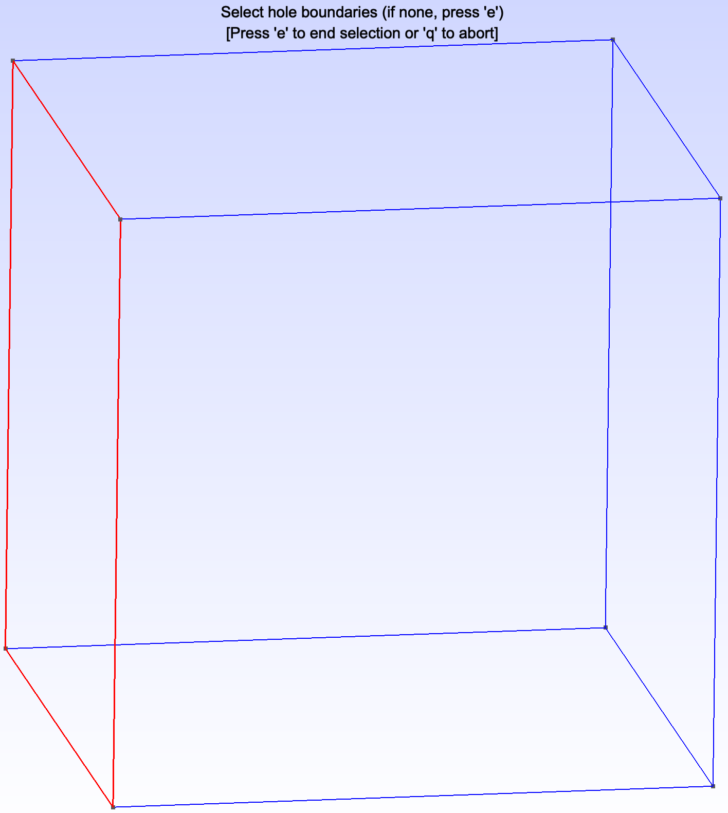
2To define surface, we need to choose the boundary lines that define the surface. Boundaries that are chosen are highlighted in red.
a.Once the boundaries are chosen, press e to register the entry. b.Repeat the procedures until all surfaces are defined. 3We have now defined all surfaces of the cube geometry.
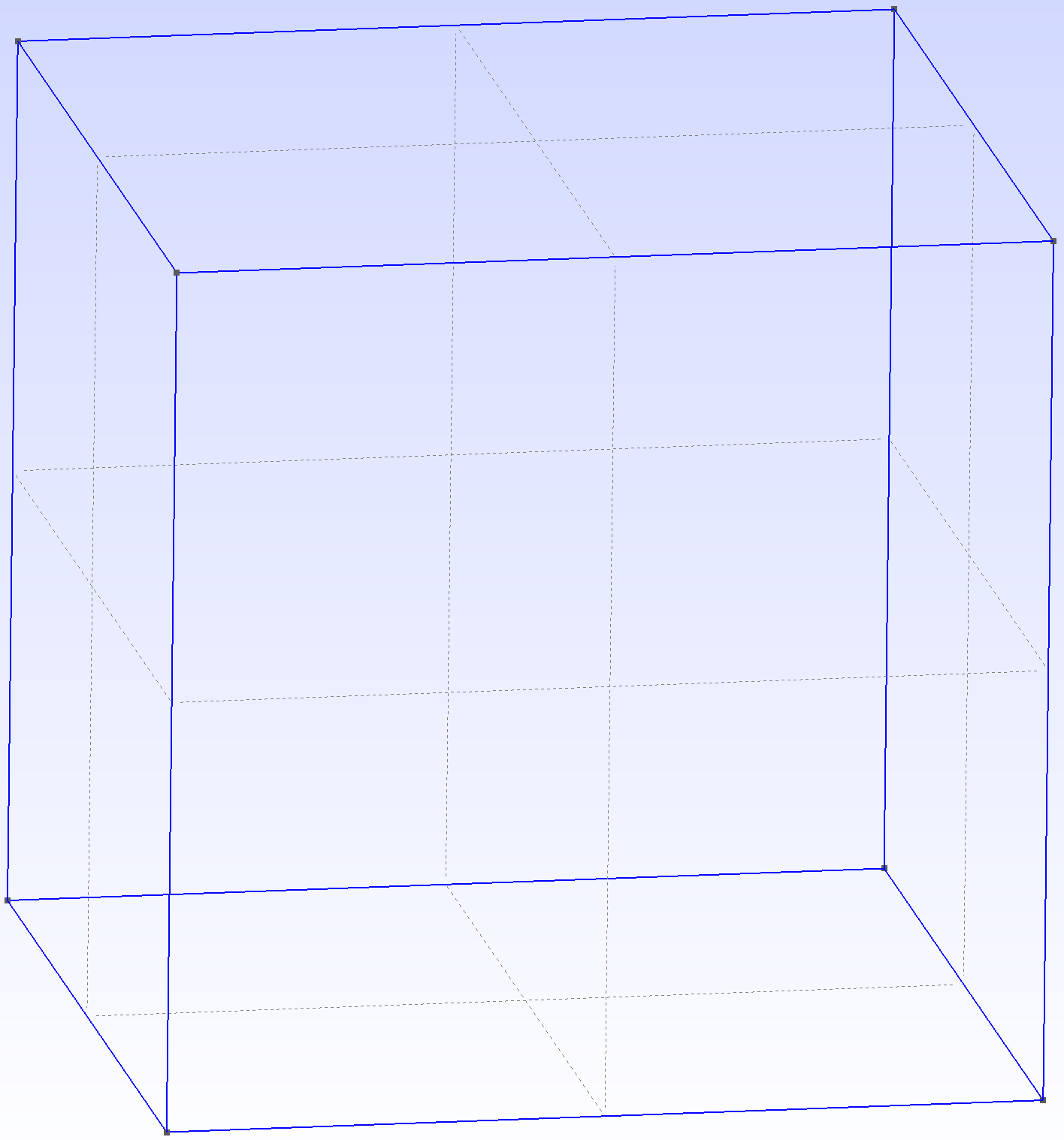
|
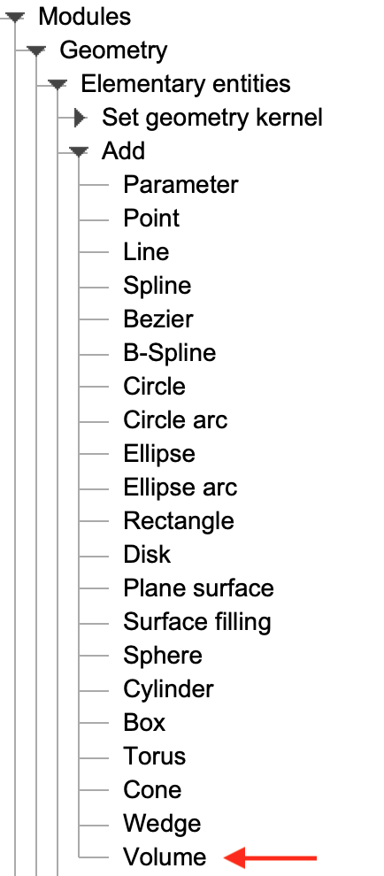
1Similar to the previous step, choose Volume on the left panel.
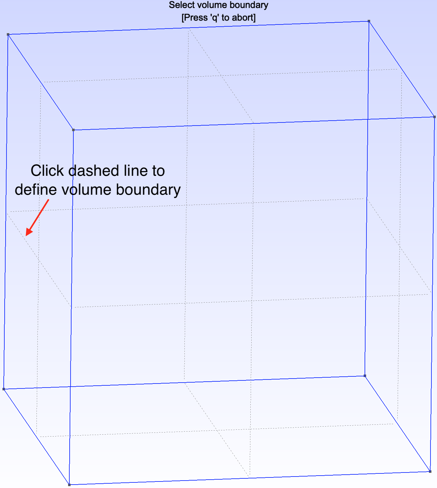
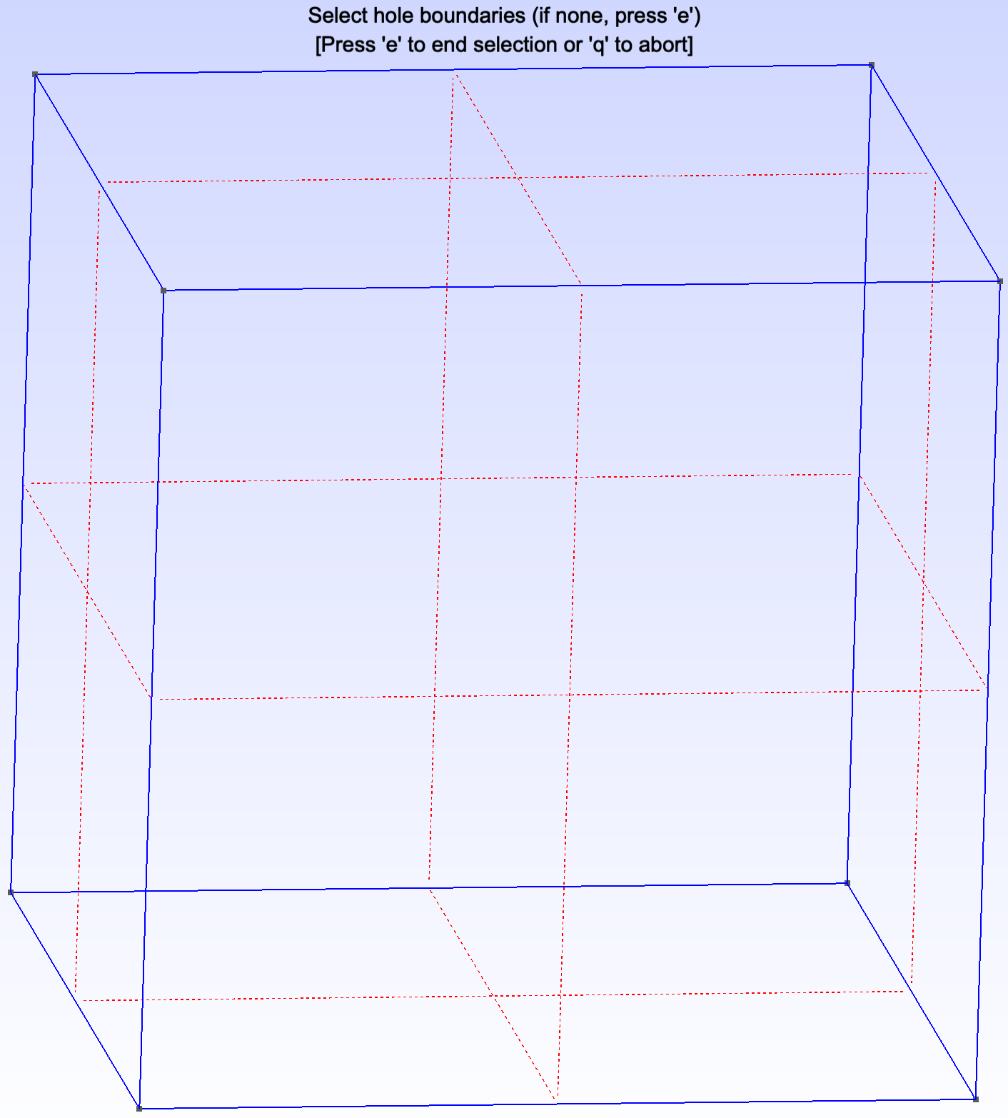
2Then, choose volume boundary. The boundary is represented by dashed lines.
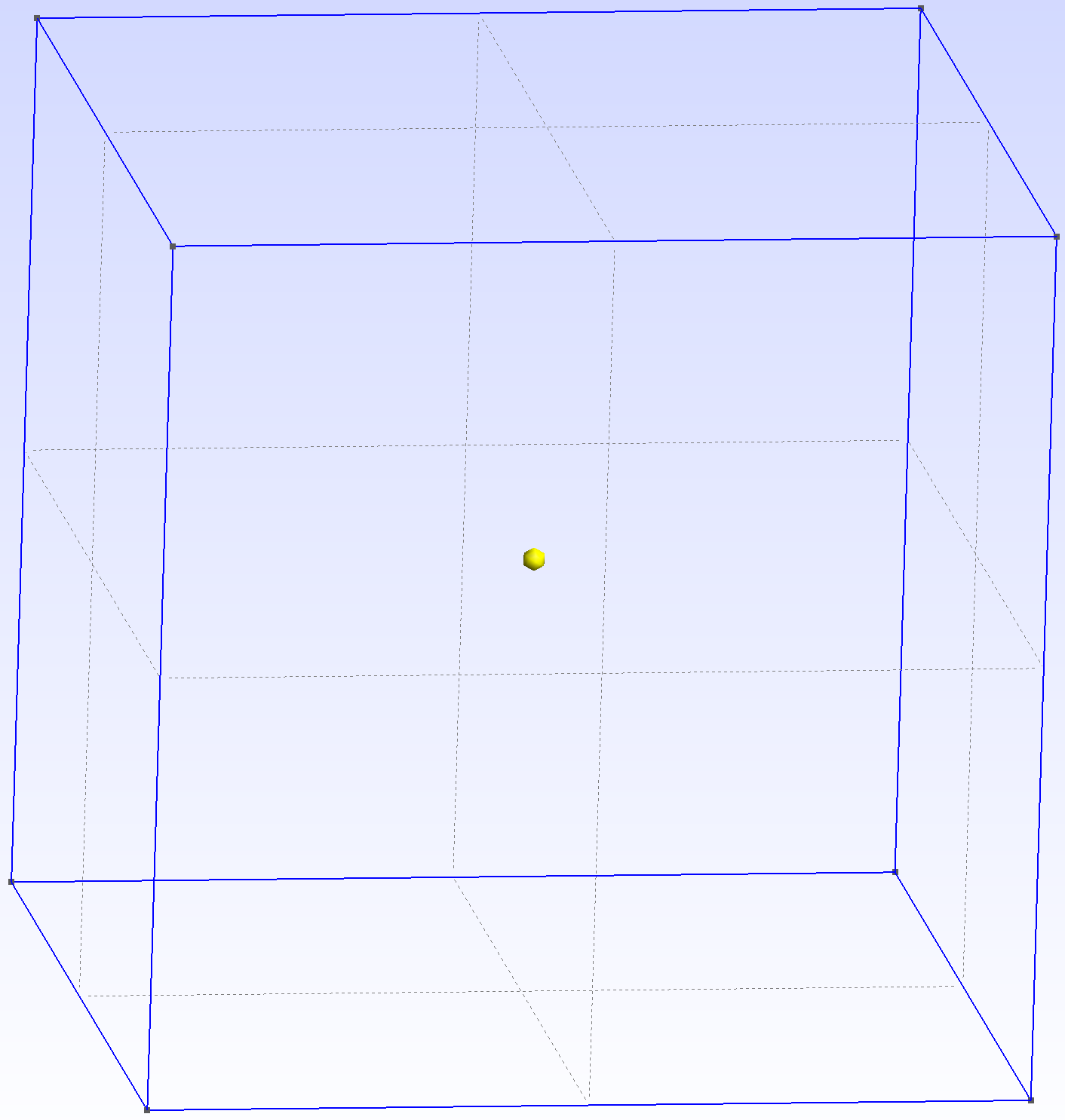
3Press e to register entry and q to abort. We have now defined the volume of cube geometry.
|
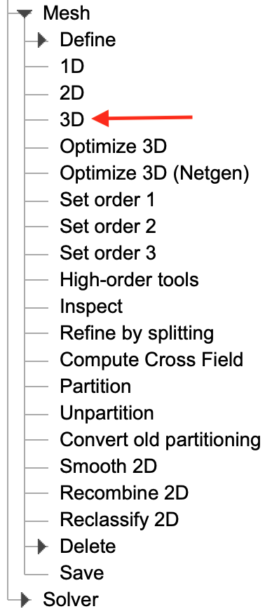
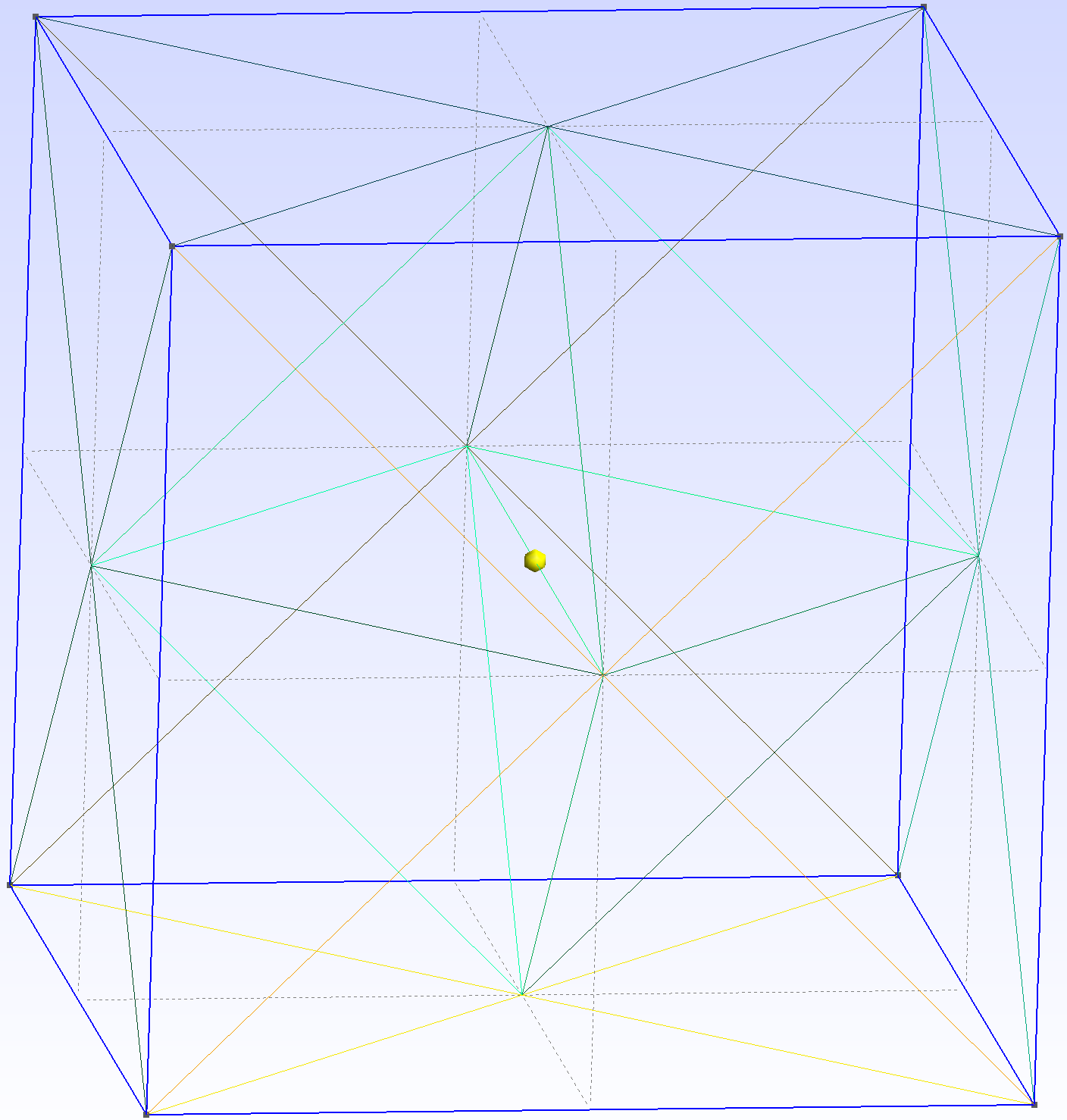
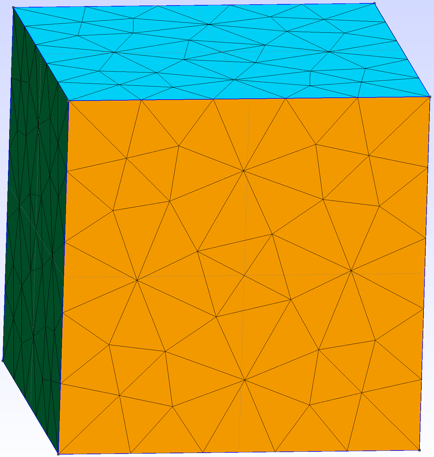
1Now, we are ready to generate unstructured mesh for the cube model. 2We can directly generate mesh by simply selecting 3D on the left panel under Mesh list.
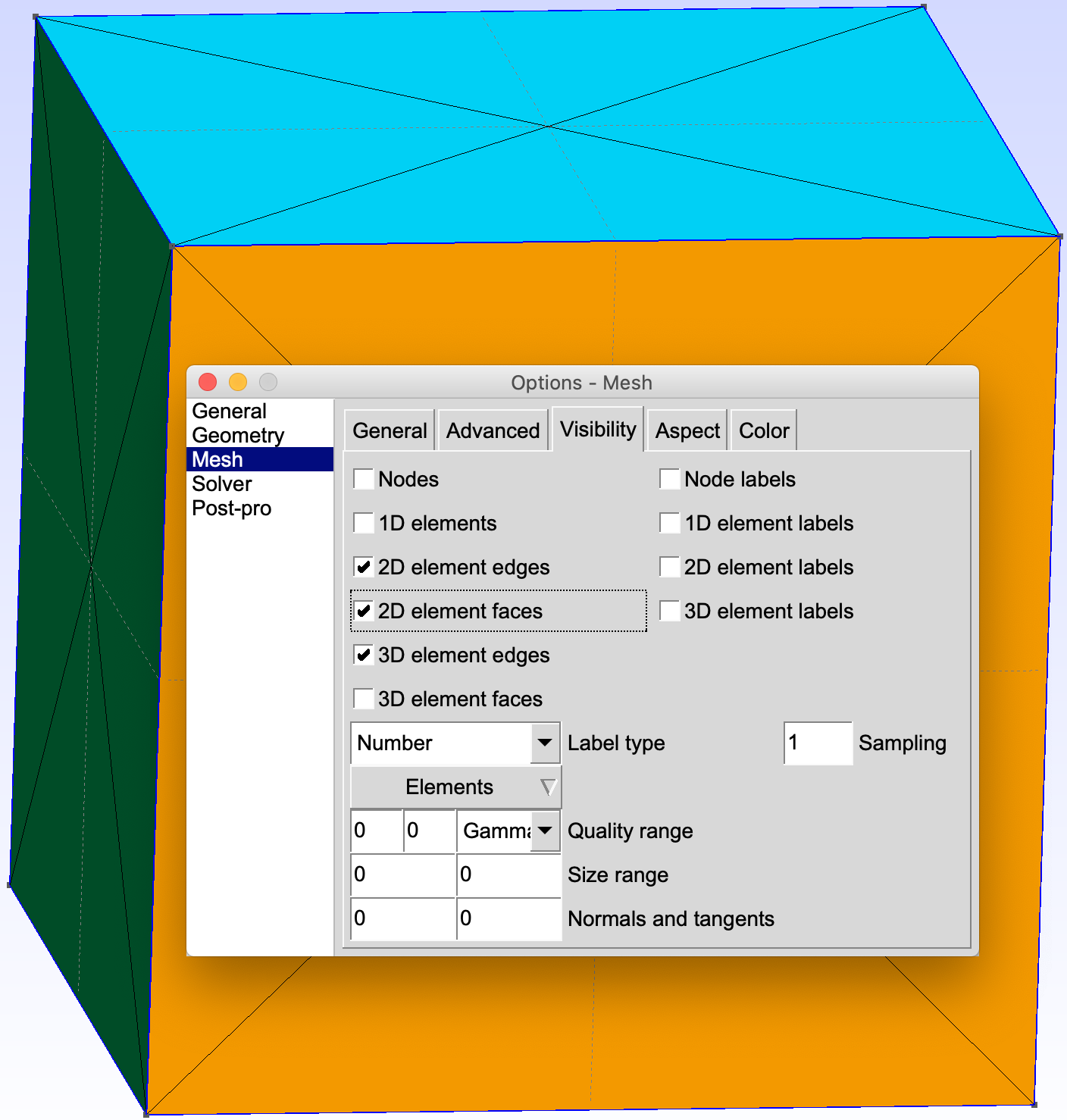
3We will then obtain the following mesh.
4We may alter the visualisation by going to Tools -> Options -> Mesh, and checking 2D Element Faces.
|
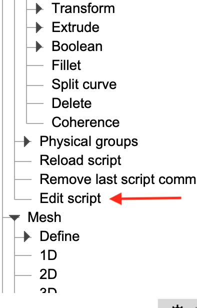
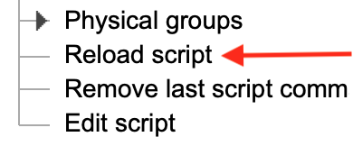
1Notice that the mesh size appears to be very coarse. We can manipulate the mesh size by modifying the script. 2On the left panel, select Edit Script.
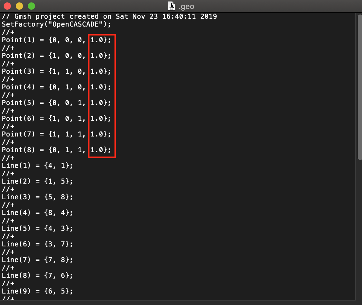
3A text file will appear, showing the history of the operations we have performed when creating the geometry. As shown in the following, the highlighted region (showing value 1.0) contains entries that are responsible for defining the mesh size surrounding each vertex point. Smaller value corresponds to smaller mesh size, and vice versa.
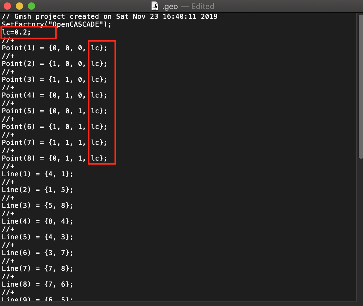
4Instead of changing the mesh size for each point, we may define a new variable within a script, as follows
5Now, the value 1.0 of each point definition has been replaced by a new variable lc, which is defined at the top. 6Save and close the file. Reload the script.
7Generate mesh by selecting 3D again. With the new value 0.2, we should expect the cube to be now discretised with smaller elements.
|

