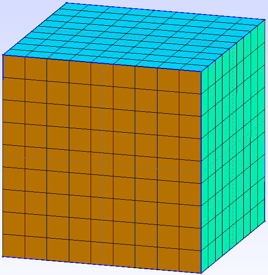
Gmsh_001_Example2a: Uniform Size Structured Mesh
Using the same cube geometry as in the Unstructured Mesh example, we will begin to define structured mesh using Transfinite tool. On the left panel, under Mesh utility, expand Define and Transfinite list.
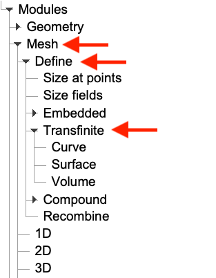
Firstly, we need to decide the discretisation size of each side of the cube geometry. To do this, we define the number of points to be used for discretisation for each side. For example, 10 points correspond to 9 element. Now, select Curve and enter 10 to define the number of points. Then, choose all sides (highlighted in red) and press e to end selection. Press q to abort.
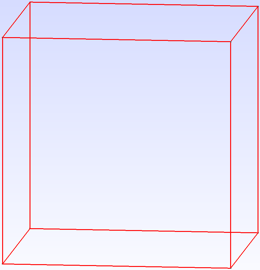
Next, select Surface in the Transfinite tool list. Each surface is added separately by pressing e. Press q when finished.
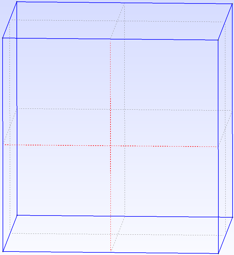
Then, select Volume in the Transfinite tool list. A small yellow ball appears to indicate the volume it represents. First, select the yellow ball. Once selected, the colour is changed into red.
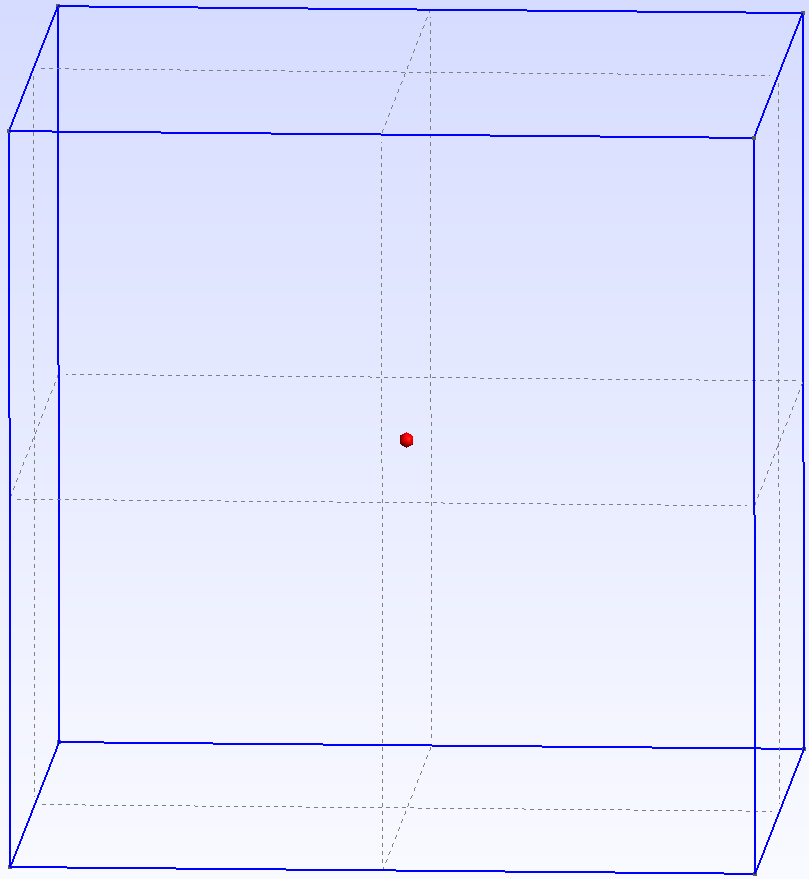
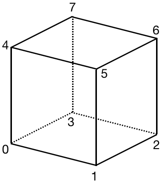
Next, we need to select all boundary points corresponding to the volume in an ordered manner. For a hexahedron, the selection order of boundary points refers to the following figure. For other shapes, please refer to this online resources.
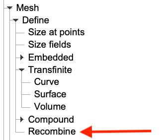
Next, to change from tetrahedra to hexahdra, we select Recombine and choose all boundary surfaces that define the cube volume. Press e and q to end selection and abort.
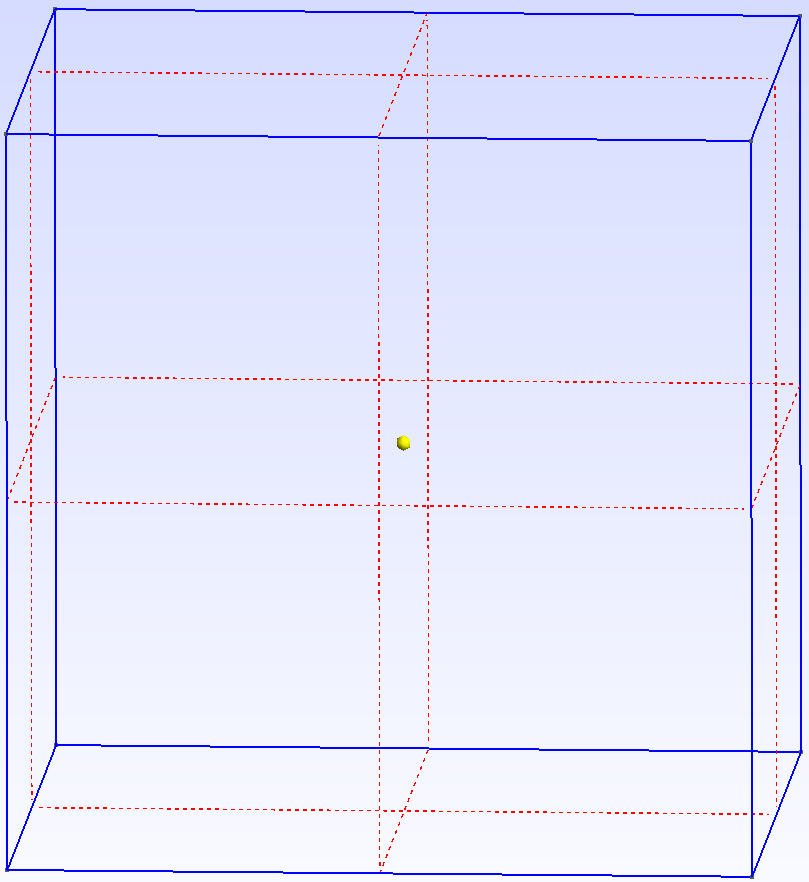
Now, select 3D to generate mesh. We may show 2D element faces for the convenience of visualisation (Tools -> Options -> Mesh -> Visibility -> Check 2D element faces)
