Gmsh_002 Gmsh Script
In this tutorial page the script for generating the geometry and mesh in Gmsh will be discussed as well as the export options. First lets have a look to the target geometry to be generated:
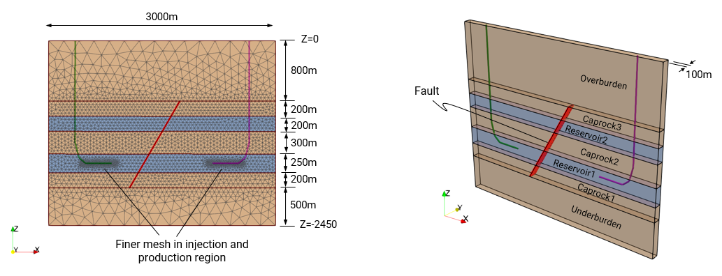
View of the geometry dimensions and the adopted formation names
The approach that we will follow for generating such geometry is:
1.Create Gmsh variables for the input parameters
2.Use 3D Box geometry entities to define the unfaulted formations
3.Define the fault plane that will be used to split the formations. For convenience this will initially be defined vertical and then a rotation according to the fault dip angle will be applied prior to the split.
4.Clean the non-used geometry entities resulting from the split
5.Definition of physical groups for latter conversion to ParaGeo geometry sets
6.Definition of mesh regions with a refined mesh size (region around well injection / production)
Script definition
Parameter Definition
The first step that we will follow is to define the Gmsh parameters / variables that later can be used in the geometry definition. Usage of Gmsh variables is advantageous for:
1.Parametrize model geometry so that variations of the geometry may be obtained by changing the input parameter values
2.Pre-calculate model input coordinates (or any other type of model input) thus keeping the definition of geometry entities more simple (e.g. a given fault point coordinate may require to calculate the sine / cosine of the fault angle multiplied by a given fault length and would be more convenient to define a variable for each coordinate of such fault point and calculate them outside and before the geometry entity definition)
The primary input parameters are defined below. Note that such primary input parameters will define the model dimensions and variations of the geometry could be latter obtained by just changing the values of these model parameters.
Script |
|
MLen = 3000 ; // Model Length MWidth = 100 ; // Model Width OveTh = 800 ; // Overburden Thickness Cap3Th = 200 ; // Caprock 3 Thickness Res2Th = 200 ; // Reservoir 2 Thickness Cap2Th = 300 ; // Caprock 2 Thickness Res1Th = 250 ; // Reservoir 1 Thickness Cap1Th = 200 ; // Caprock 1 Thickness UndTh = 500 ; // Underburden Thickness
Fdeg = 60 ; // Fault angle in degrees Fazi = 0; // Rotation azimut for the fault in degrees FaultX = 1300 ; // Fault X coord at half depth of the reservoir
lc01 = 50 ; // Mesh size at fault intersections lc02 = 50; // Mesh size for reservoir layers (external boundaries) lc03 = 70 ; // Mesh size Buffers external lc04 = 200; // Mesh size Overburden Top and Base
|
•The primary input parameters defined in this case comprise: 1.Model length and width 2.Thickness for all the formations 3.Fault dip angle, azimuth and X coordinate for the initial location (for convenience fault is initially defined vertical and then a rotation is applied) 4.Variables to define characteristic length (mesh size) at selected points
•Note that in Gmsh scripts usage of double slash // indicates that the remaining characters in that line are comments
•Note that in Gmsh scripts a semicolon ; indicates the end of a given command. |
From the previously defined primary input parameters we can calculate dependent variables / parameters to facilitate geometry definition. Those are defined below:
Script |
|
Frad = Fdeg*Pi/180 ; // Fault dipping angle in radians Fazirad = Fazi*Pi/180 ; // Rot. azimuth for the fault in radians
DCap3 = -OveTh ; // Depth top Caprock 3 DRes2 = DCap3-Cap3Th ; // Depth top Reservoir 2 DCap2 = DRes2-Res2Th ; // Depth top Caprock 2 DRes1 = DCap2-Cap2Th ; // Depth top Reservoir 1 DCap1 = DRes1-Res1Th ; // Depth top Caprock 1 DUnd = DCap1-Cap1Th ; // Depth top Underburden DBase = DUnd-UndTh ; // Depth Model base
|
•The additional dependent variables defined to facilitate geometry entity definition comprise: 1.Fault angles in radians to define the rotation to be applied to the fault plane. Note that all operations in Gmsh must be defined in radians but the input parameters were initially defined in degrees for convenience. 2.Depths for all the formation tops calculated from the previously defined formation thicknesses |
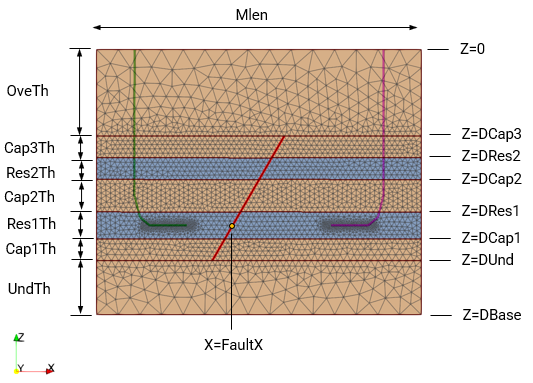
View of the geometry with some of the defined parameters
Definition of the formations (unfaulted)
The formations are initially defined as continuum (unfaulted) and then a fault plane will be defined to split the formations.
Script |
|
SetFactory("OpenCASCADE");
Box(1) = {0, 0, 0, MLen, MWidth, DCap3}; Box(2) = {0, 0, DCap3, MLen, MWidth, -Cap3Th}; Box(3) = {0, 0, DRes2, MLen, MWidth, -Res2Th}; Box(4) = {0, 0, DCap2, MLen, MWidth, -Cap2Th}; Box(5) = {0, 0, DRes1, MLen, MWidth, -Res1Th}; Box(6) = {0, 0, DCap1, MLen, MWidth, -Cap1Th}; Box(7) = {0, 0, DUnd, MLen, MWidth, -UndTh};
|
•Note that to be able to use pre-defined geometry entities (and thus save time by avoiding to define each point, line, surface and volume) the command SetFactory("OpenCASCADE"); must be specified. This is recommended to be defined at the top of the script. •Seven box geometry entities are introduced in order to represent the seven formations. In the Box(n) command, n is the entity number and then the input components are {X, Y, Z, dX, dY, dZ} where the first three components X, Y and Z indicate the coordinates of the starting box corner and the subsequent ones dX, dY and dZ indicate the increment in the coordinates for the opposed box corner (the diagonal). •Note how each formation is defined with the corner starting at X=0, Y=0 and Z corresponding to the depth of each formation top and the opposite point defined according to model length, model width and formation thickness. •The Box entities may optionally be added from Gmsh graphical interface by clicking on Modules/Geometry/Elementary entities/Add/Box. Then in the pop up menu the 6 arguments must be entered and then click on the "Add" button. It can be observed that the corresponding line of script is added after clicking the "Add" button. |
Definition of the fault plane
A fault plane to split the formations will be defined. For convenience initially the fault will be defined vertical and then a rotation according to the fault dipping angle will be applied. This simplifies the input values and enables parametrisation of the fault geometry.
Script |
|
Point(1)= {FaultX, MWidth, DBase, lc01}; Point(2)= {FaultX, 0 , DBase, lc01}; Point(3)= {FaultX, MWidth, 0 , lc01}; Point(4)= {FaultX, 0 , 0 , lc01};
Line(1) = {3, 4}; Line(2) = {4, 2}; Line(3) = {2, 1}; Line(4) = {1, 3};
Curve Loop(1) = {1, 2, 3, 4}; Plane Surface(1) = {1};
// Fault plane rotation according to dipping angle Rotate {{0, 1, 0}, {FaultX, 0, DRes1-(0.5*Res1Th)}, Pi/2-Frad} { Surface{1}; }
|
•Note that the fault plane will be defined by defining 4 points, then joining them with lines and then using the lines to define a plane surface. •Initially the fault plane will be defined vertical, parallel to the YZ plane, going from the base of the model (Z = Dbase) to the top (Z = 0), going all across model width and located at a previously defined X coordinate (FaultX) •Note that if there are previously defined geometry entities (e.g. the seven boxes), points IDs 1, 2, 3 and 4 would be already used (as well as the assigned line IDs joining them) and therefore theoretically we would require to find the next ID number available for each geometry entity type. However because Gmsh reads the script from top to bottom we can paste the present section of the script before the Box commands for formation definition. In such a way, because fault point definition comes first, the point ID numbers for the first box defined will be 5 to12 as opposed to 1 to 8. Note that if the graphical user interface is used to introduce the fault plane points Gmsh would automatically assign them the next subsequent ID number available. •A rotation operation is applied to the fault plane. This can be done in the graphical user interface by clicking on Modules/Geometry/Elementary entities/Transform/Rotate and then selecting the geometry entity to which the rotation will be applied (then introduce the input values in the pop up window). •The arguments to be introduced in the Rotate command are the three components defining the rotation axis direction {0, 1, 0} in this case indicating that the rotation will be parallel to the Y axis; followed by the centre of rotation {FaultX, 0, Dres1-(0.5*Res1Th)} in this case; then the rotation angle (pi/2-Frad) and finally specifying the geometry entity that will be applied the rotation. |
Split of faulted formations
Here we split the formations which should be faulted using the Boolean operation "Fragments" and then we delete the remaining unused surfaces from the fault plane.
Script |
|
BooleanFragments{ Volume{2}; Volume{3}; Volume{4}; Volume{5}; Volume{6}; Delete; }{ Surface{1}; Delete; }
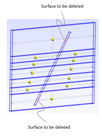
Recursive Delete { Surface{91}; Surface{92}; }
Coherence; // This is done to ensure continuum volumes
|
•A BooleanFragments operation is applied to cut volumes 2, to 6 (all layers except the overburden and underburden). This may be done in the graphical user interface in Modules/Geometry/Elementary entities/Boolean/Fragments then select the objects (the formations) and the tool (fault plane). The command format is: BooleanFragments{ List of object entities ; Delete (if applicable); } { List of tool entities; Delete (if applicable); } •Note that both, the object and the tool are requested to be deleted. If we don't do that, then the original unfaulted formation volumes would be preserved in addition to the new split ones. •A recursive delete is applied to the two fault plane surfaces that are generated from the fragments operation and wont be used. This may be done in the graphical interface by clicking on Modules/Geometry/Elementary entities/Delete. •A Coherence command is used to ensure continuity in the domain (note that we will split the contact surface for the fault during conversion to ParaGeo). This can be done from the graphical interface in Modules/Geometry/Elementary entities/Coherence
Details of the two surfaces to be deleted |
Defining physical groups
Definition of physical groups (groups of geometry entities) is recommended in order to be able to generate equivalent Geometry_set data after conversion of the exported mesh to ParaGeo format.
Script |
|
Physical Surface("Base", 167) = {42}; Physical Surface("South", 192) = {96, 108, 110, 74, 78, 65, 69, 56, 60, 102, 104, 89}; Physical Surface("North", 193) = {97, 109, 112, 75, 81, 66, 72, 57, 63, 103, 106, 90}; Physical Surface("East", 194) = {95, 111, 80, 71, 62, 105, 88}; Physical Surface("West", 195) = {94, 107, 73, 64, 55, 101, 87}; Physical Surface("Fault", 196) = {86, 77, 68, 59, 49}; Physical Surface("Overburden", 197) = {93}; Physical Surface("Caprock3", 198) = {91, 92}; Physical Surface("Reservoir2", 199) = {48, 51}; Physical Surface("Caprock2", 200) = {58, 61}; Physical Surface("Reservoir1", 201) = {67, 70}; Physical Surface("Caprock1", 202) = {76, 79}; Physical Surface("Underburden", 203) = {99, 100};
Physical Volume("Underburden_Vol", 205) = {7}; Physical Volume("Caprock1_Vol", 206) = {16, 17}; Physical Volume("Reservoir1_Vol", 207) = {14, 15}; Physical Volume("Reservoir2_Vol", 208) = {10, 11}; Physical Volume("Caprock2_Vol", 209) = {12, 13}; Physical Volume("Caprock3_Vol", 210) = {8, 9}; Physical Volume("Overburden_Vol", 211) = {1};
|
•Physical groups are defined for: oModel boundaries oFormation tops oFault plane oEach of the formations (optional but recommended) •This is more easily done via the graphical interface by clicking on Modules/Geometry/Physical groups/Add/Surface. Then a pop up window will appear and we should: oIntroduce the name of the physical surface (e.g. Fault) oSelect by clicking with the mouse all the surfaces to be grouped in a physical surface (e.g. all surfaces defining the fault). If a wrong surface is clicked by mistake you can press the key "u" in the keyboard to undo the last selection. oWhen all surfaces for the physical group are selected click "e" to end selection. All the surfaces will now appear as unselected, the corresponding Physical Surface command will appear on the script and Gmsh is ready to proceed with the definition of the next physical group by repeating the procedure. •The same procedure may be used to add Physical groups for the formations (Physical volumes). Note that this is optional (recommended) as at the moment conversion of Volume geometry sets is not supported. However Physical volumes facilitate visualisation of the volume numbers assigned to each of the formations which is required during the conversion stage. This will be explained in the next manual page.
|
After the physical groups have been added, it is recommended to double-check that they are correctly defined (e.g. there is not a missing surface in a given physical group, or a given surface is included in the wrong physical group, etc). This can easily be done by:
1.Meshing the geometry (click on Modules/Mesh/3D). This will generate a coarse mesh and will facilitate to visualize/differentiate the different surfaces / entities.
2.Going to the top menu and select Tools/Visivility. A pop up window like the one shown below will be displayed.
3.In the drop-down menu select to list the Physical Groups
4.Select the physical group you wish to display and click the "Apply" button. Only the selected Physical surface will be displayed.
5.Note that multiple physical groups may be selected by holding "Ctrl" key on the keyboard while mouse left-clicking on the selected entities
After the definition of the physical groups have been checked you can click on Modules/Geometry/Reload script to remove the mesh and continue with the geometry definition.
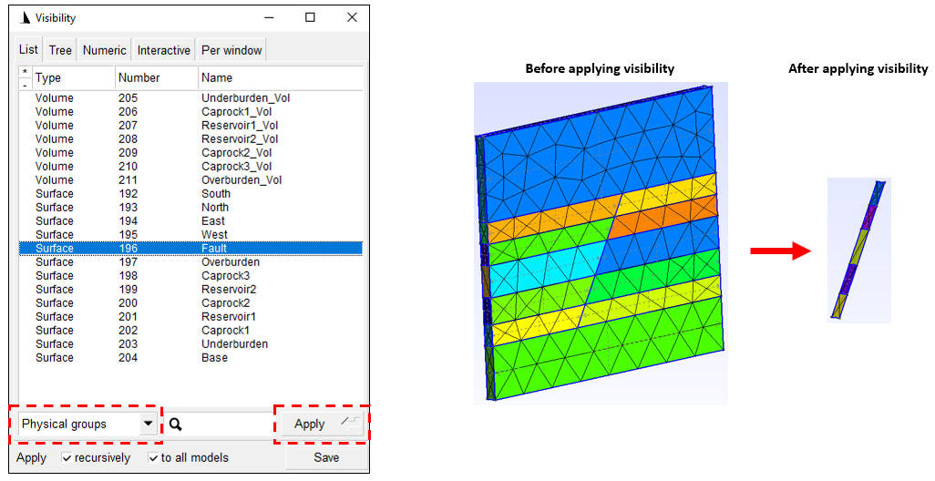
Pop up window for visibility selection and its application to the "Fault" physical surface
Note that if physical volumes are defined
Defining Mesh Sizes
The mesh size will be defined in two stages. First the main mesh will be defined by defining element sizes at geometry points and then mesh regions interior to the model with refined mesh size will be defined using "Fields".
Script |
|
MeshSize {93, 94, 87, 88, 81, 82, 75, 76, 65, 66, 67, 68, 69, 77, 83, 71, 89, 78, 84, 90, 61, 73, 79, 64, 85, 74, 80, 86} = lc01; MeshSize {95, 98, 99, 102, 104, 105, 108, 109} = lc02; MeshSize {96, 97, 100, 101, 103, 106, 107, 110} = lc03;
|
•The definition of primary element mesh sizes is more convenient to be done via the graphical interface by selecting Modules/Mesh/Define/Size at points, then: oWriting the element size to be assigned (in theis case one of the three previously defined parameters/variables; lc01, lc02 and lc03) oSelecting with the mouse left click all the points to be assigned such element size (note you can hold "Ctrl" key and drag left mouse button to select multiple points at once) oOnce all points to be assigned an element size are selected click "e" to end selection. The corresponding command will appear on the script. •Note that if a point is missing element size assignment it can latter be added individually by repeating the procedure for such point •Note that if a given point is assigned an element size and latter is assigned a different size in another command, the latter will overwrite the former
|
At this point an usable mesh is generated but we are interested to define mesh regions with smaller mesh sizes to improve the resolution around the area of injection / and production. This is discussed below.
Script |
|
// Definition of Field 1 Field[1] = Box; Field[1].Thickness = 180; Field[1].VIn = 15; Field[1].VOut = 50; Field[1].XMax = 910; Field[1].XMin = 415; Field[1].YMax = 110; Field[1].YMin = -10; Field[1].ZMax = -1595; Field[1].ZMin = -1655;
// Definition of Field 2 Field[2] = Box; Field[2].Thickness = 180; Field[2].VIn = 15; Field[2].VOut = 50; Field[2].XMax = 2585; Field[2].XMin = 2090; Field[2].YMax = 110; Field[2].YMin = -10; Field[2].ZMax = -1595; Field[2].ZMin = -1655;
// Definition of Field 3 Field[3] = Min; Field[3].FieldsList = {1, 2}; Background Field = 3;
|
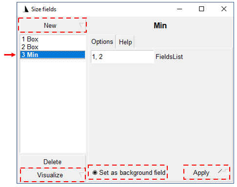
•Fields are used to define regions within the model with finer mesh sizes. Definition of fields is more easily done via the graphical interface by clicking on Modules/Mesh/Define/Size at fields. Then the Fields window will pop up and we should click on "New" button to add a new field. •Note that only one Field can be set as background field and hence only one can be used to define mesh sizes. In case that we need to combine more than one field we need to use either a Field type "Max" or type "Min" and set it as the background field (as done for the present case). •In this case 2 Fields of type "Box" will be used each to define smaller mesh size within a hexahedral shaped box located in the domain as defined by the input box coordinates. The input properties for the field are: oVIn and VOut defining the element sizes within and outside the box respectively oThickness defining the thickness/size of a bounding layer around the box for controlling the change in element sizes from VIn to VOut. In other words, is like defining a larger box containing the actual Field box where the thickness is the distance between each side of the box to the bounding box. Larger values will give more gradual transition in element sizes whereas smaller values will lead to a sudden transition. In this case a value of 180 indicates that the element size will gradually change from 15m to 50m over a distance of 180 m from the edge of the Field box. oXMin, Xmax, Ymin, Ymax, Zmin, Zmax defining the minimum and maximum coordinates respectively for two opposite box corners •Then because only one field can be set as background field for the mesh, a Field of type "Min" will be used to create a Field that returns the minimum element size at each location from the combination of the input (previously defined fields). In this case we specify Fields 1 and 2 (the two previously defined box fields). The resulting field considers an element size of 15 m withing the two boxes locations which gradually change to an element size of 50 m outside the boxes over a distance of 180 m. •Note that any field can be visualised as an element size contour map in the graphical interface by selecting the field in the Field window, then click on "Visualize" and then click on "Create new view" (see the figure below). Note that to properly visualise the field any generated mesh must be hidden (or alternatively the script may be reloaded).
View of the "Size fields" window with the Field 3 selected
|

View of the mesh before and after application of mesh refinement via fields
After the fields are defined the mesh is generated by clicking on Modules/Mesh/3D. Then export of the mesh must be performed in Abaqus format (.inp) to enable conversion to ParaGeo format. This has to be done from the top menu by going to File/Export. This will display the export window where the export file name must be defined and the file type must be set as "Mesh - Abaqus (.inp)". Note that although the file type is set as .inp this only indicates the format for the mesh data, but not the file extension of the output file. In this case the defined file extension is defined manually in the output name as .mesh.
After clicking on "Save" button the "Abaqus INP Options" window will appear (see figure below). In there both options must be active:
•Save all elements: This will output all the elements to the .inp file. If not activated only the elements that are included in a Physical group would be output.
•Save groups of nodes: This will generate an Abaqus NSET for each physical group defined in Gmsh. Those NSETs latter will be converted to ParaGeo Geometry_set data.
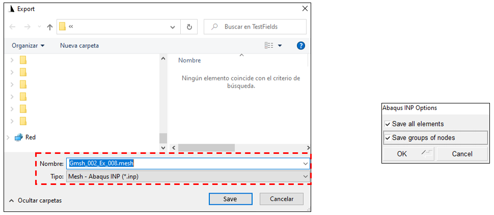
View of the Export and Abaqus INP Options windows

