Group_data
Data Structure: Group_data |
|
Description |
Definition data for element groups |
Usage |
Group_data NUM=ival where ival is the data structure number |
Description |
Overview The Group_data structure is used for grouping the elements from user selected geometric entities (i.e. surfaces in 2D, volumes in 3D) which will have common assignments (i.e. material, type of element, etc.). In geological applications each stratigraphy unit will usually be defined with a different group. Geometry entities that define stratigraphy units which are discontinuous (e.g. a stratigraphy unit which has been pierced by a salt diapir and is currently being defined by 2 surfaces) are usually defined with the same group. The definition data for element groups includes: •Element type •Element formulation type; e.g. Average volume element formulation for triangle and tetrahedra •Material assignment •Geometry assignment; i.e. a list of surfaces (2-D) or volumes (3-D) that define the group •The porous flow type; i.e. drained, undrained, coupled, etc •A flag to state whether gravity loading should be applied to the group •X-axis axisymmetric flag •Coordinate system assignment if the material is transverse isotropic or orthotropic Notes •A Group_data structure must be defined for each active group
Examples demonstrating the usage of Group_data include: •All examples
|
| Group_name Element group name |
Usage |
||||
|
||||
Description |
||||
Name assigned to the group (maximum characters 64). If specified the group can then be referenced directly using the group name in several operations; e.g. stratigraphy definition.
|
| Element_type_number (Depreciated for Element_type) |
Usage |
||||
|
||||
Description |
||||
Integer number that identifies the element type. Valid type numbers are: • 1 - Tetrahedral Element (TET4) (All fields) • 2 - Prism (Pentrahedral) Element (WEDGE6) (Geomechanical Explicit, Geomechanical Implicit) • 3 - Hexahedral Element (HEX8) (All fields) • 4 - Pyramid (Pentrahedral) Element (PENT5) (Geomechanical Explicit, Geomechanical Implicit) • 6 - Plane Strain Triangle Element (TPM3) (All fields) • 7 - Plane Strain Quadrilateral Element (QPM4) (All fields) • 8 - Axisymmetric Triangle Element (TAX3) (All fields) • 9 - Axisymmetric Quadrilateral Element (QAX4) (All fields) • 10 - Plane Strain Average Volume Strain Triangle Element (TPM3V) (All fields*) • 11 - Axisymmetric Average Volume Strain Triangle Element (TAX3V) (All fields) • 12 - Tetrahedral Average Volume Strain Element (TET4V) (All fields*) • 13 - Bar Element (BAR2D) (Geomechanical Explicit) • 14 - Bar Element (BAR3D) (Geomechanical Explicit) • 15 - Plane Strain Element (TPM6) (Geomechanical Implicit) • 16 - Tetrahedral Element (TET10) (Geomechanical Implicit) • 17 - Axisymmetric Triangle Element (TAX6) (Geomechanical Implicit) • 18 - Plane Strain Quadrilateral Element (QPM8) (Geomechanical Implicit) • 19 - Axisymmetric Quadrilateral Element (QAX8) (Geomechanical Implicit) • 20 - Prism (Pentahedral) Element (WEDGE15) (Geomechanical Implicit) • 21 - Hexahedral Element (HEX20) (Geomechanical Implicit) • 22 - Plane Strain Mixed Element Formulation (TPM6M) (Geomechanical Implicit) • 23 - Plane Strain Quadrilateral Mixed Element Formulation (QPM8M) (Geomechanical Implicit) • 24 - Plane Strain Quadrilateral Mixed Element Formulation (QPM9M) (Geomechanical Implicit) • 25 - Tetrahedral Mixed Element Formulation (TET10M) (Geomechanical Implicit) • 26 - Prism (Pentahedral) Mixed Element Formulation (WEDGE15M) (Geomechanical Implicit) • 27 - Hexahedral Mixed Element Formulation (HEX20M) (Geomechanical Implicit) • 28 - Plane Strain Triangle Mixed Element Formulation (TPM3M) (Geomechanical Implicit) • 29 - Plane Strain Quadrilateral Mixed Element Formulation (QPM4M) (Geomechanical Implicit) • 30 - Tetrahedral Mixed Element Formulation (TET4M) (Geomechanical Implicit) • 31 - Pyramid (Pentrahedral) Mixed Element Formulation (PENT5M) (Geomechanical Implicit) • 32 - Prism (Pentrahedral) Mixed Element Formulation (WEDGE6M) (Geomechanical Implicit) • 33 - Hexahedral Element Mixed Element Formulation (HEX8M) (Geomechanical Implicit) • 34 - Tetrahedral Element (TPM3D) (Geomechanical Explicit)
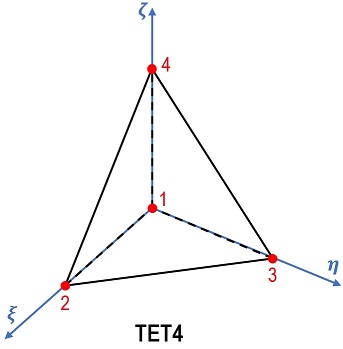
Notes •"Bbar" is the default Mesh_integration_type for implicit QPM4, QAX4 and HEX8 elements. •* TPM3V and TET3V are changed to TPM3 and TET3, respectively, for implicit analysis. •The TET4 element topology and the corresponding shape functions are illustrated as follows:
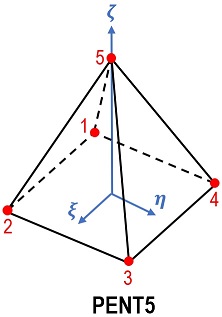
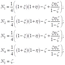
•The PENT5 element topology and the corresponding shape functions are illustrated as follows:
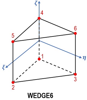
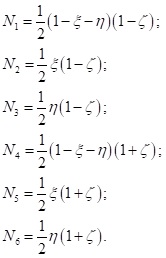
•The WEDGE6 element topology and the corresponding shape functions are illustrated as follows:
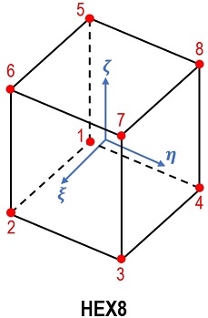
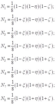
•The HEX8 element topology and the corresponding shape functions are illustrated as follows:
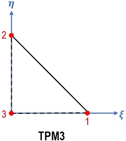
•The TPM3 element topology and the corresponding shape functions are illustrated as follows:
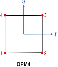
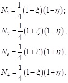
•The QPM4 element topology and the corresponding shape functions are illustrated as follows:
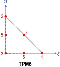
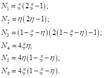
•The TPM6 element topology and the corresponding shape functions are illustrated as follows:
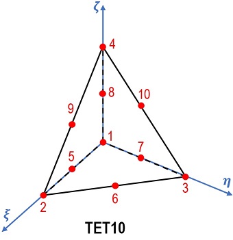
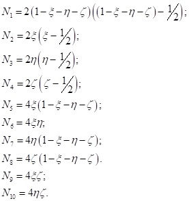
•The TET10 element topology and the corresponding shape functions are illustrated as follows:
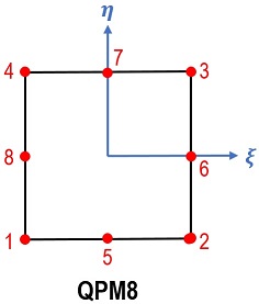
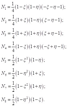
•The QPM8 element topology and the corresponding shape functions are illustrated as follows:
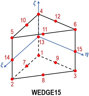
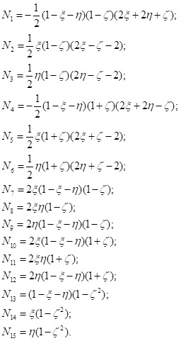
•The WEDGE15 element topology and the corresponding shape functions are illustrated as follows:
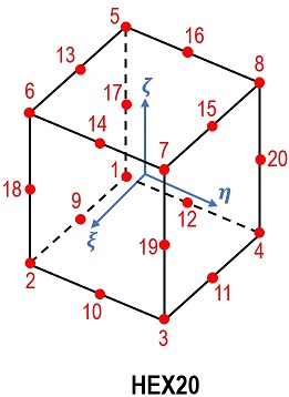
•The HEX20 element topology and the corresponding shape functions are illustrated as follows:
|
| Element_type Element type (Either Element_type or Element_type_number Compulsory) |
Usage |
||||
|
||||
Description |
||||
Character name that identifies the element type. Valid element types are: • TET4 - Tetrahedral Element (TET4) (All fields) • WEDGE6 - Prism (Pentrahedral) Element (WEDGE6) (Geomechanical Explicit, Geomechanical Implicit) • HEX8 - Hexahedral Element (HEX8) (All fields) • PENT5 - Pyramid (Pentrahedral) Element (PENT5) (Geomechanical Explicit, Geomechanical Implicit) • TPM3 - Plane Strain Triangle Element (TPM3) (All fields) • QPM4 - Plane Strain Quadrilateral Element (QPM4) (All fields) • TAX3 - Axisymmetric Triangle Element (TAX3) (All fields) • QAX4 - Axisymmetric Quadrilateral Element (QAX4) (All fields) • TPM3V - Plane Strain Average Volume Strain Triangle Element (TPM3V) (All fields*) • TAX3V - Axisymmetric Average Volume Strain Triangle Element (TAX3V) (All fields) • TET4V - Tetrahedral Average Volume Strain Element (TET4V) (All fields*) • BAR2D - Bar Element (BAR2D) (Geomechanical Explicit) • BAR3D - Bar Element (BAR3D) (Geomechanical Explicit) • TPM6 - Plane Strain Element (TPM6) (Geomechanical Implicit) • TET10 - Tetrahedral Element (TET10) (Geomechanical Implicit) • TAX6 - Axisymmetric Triangle Element (TAX6) (Geomechanical Implicit) • QPM8 - Plane Strain Quadrilateral Element (QPM8) (Geomechanical Implicit) • QAX8 - Axisymmetric Quadrilateral Element (QAX8) (Geomechanical Implicit) • WEDGE15 - Prism (Pentahedral) Element (WEDGE15) (Geomechanical Implicit) • HEX20 - Hexahedral Element (HEX20) (Geomechanical Implicit) • TPM6M - Plane Strain Mixed Element Formulation (TPM6M) (Geomechanical Implicit) • QPM8M - Plane Strain Quadrilateral Mixed Element Formulation (QPM8M) (Geomechanical Implicit) • QPM9M - Plane Strain Quadrilateral Mixed Element Formulation (QPM9M) (Geomechanical Implicit) • TET10M - Tetrahedral Mixed Element Formulation (TET10M) (Geomechanical Implicit) • WEDGE15M - Prism (Pentahedral) Mixed Element Formulation (WEDGE15M) (Geomechanical Implicit) • HEX20M - Hexahedral Mixed Element Formulation (HEX20M) (Geomechanical Implicit) • TPM3M - Plane Strain Triangle Mixed Element Formulation (TPM3M) (Geomechanical Implicit) • QPM4M - Plane Strain Quadrilateral Mixed Element Formulation (QPM4M) (Geomechanical Implicit) • TET4M - Tetrahedral Mixed Element Formulation (TET4M) (Geomechanical Implicit) • PENT5M - Pyramid (Pentrahedral) Mixed Element Formulation (PENT5M) (Geomechanical Implicit) • WEDGE6M - Prism (Pentrahedral) Mixed Element Formulation (WEDGE6M) (Geomechanical Implicit) • HEX8M - Hexahedral Element Mixed Element Formulation (HEX8M) (Geomechanical Implicit) • TPM3D - Tetrahedral Element (TPM3D) (Geomechanical Explicit)
Notes •"Bbar" is the default Mesh_integration_type for implicit QPM4, QAX4 and HEX8 elements. •* TPM3V and TET3V are changed to TPM3 and TET3, respectively, for implicit analysis. •The TET4 element topology and the corresponding shape functions are illustrated as follows:
•The PENT5 element topology and the corresponding shape functions are illustrated as follows:
•The WEDGE6 element topology and the corresponding shape functions are illustrated as follows:
•The HEX8 element topology and the corresponding shape functions are illustrated as follows:
•The TPM3 element topology and the corresponding shape functions are illustrated as follows:
•The QPM4 element topology and the corresponding shape functions are illustrated as follows:
•The TPM6 element topology and the corresponding shape functions are illustrated as follows:
•The TET10 element topology and the corresponding shape functions are illustrated as follows:
•The QPM8 element topology and the corresponding shape functions are illustrated as follows:
•The WEDGE15 element topology and the corresponding shape functions are illustrated as follows:
•The HEX20 element topology and the corresponding shape functions are illustrated as follows:
|
| Material_number Material number |
Usage |
||||
|
||||
Description |
||||
Material number to be assigned to the group. Alternatively the group may be assigned a material via Material_name
|
| Material_name Material name |
Usage |
||||
|
||||
Description |
||||
Name of material to be assigned to the group. Alternatively the group may be assigned a material via Material_number
|
| Facies_id Facies ID number |
Usage |
||||
|
||||
Description |
||||
Facies ID number to be assigned to the group. Alternatively the group may be assigned a material via Material_name
|
| Porous_flow_type Porous flow type |
Usage |
||||
|
||||
Description |
||||
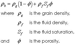
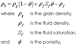
The porous flow type defines how the pore space and pore fluid should be treated for the group in the geomechanical field. Valid types are: • 0 - Non porous material. Bulk density defined by the value specified in the grain density • 1 - Dry porous material. Bulk density defined using grain density and porosity • 2 - Drained with prescribed pore pressure (both grain density and fluid density must be specified) • 3 - Undrained analysis (both grain density and fluid density must be specified) • 4 - Coupled geomechanical/porous flow analysis where porous flow field is solved (both grain density and fluid density must be specified) • 5 - Drained analysis with hydrostatic pore pressure using buoyant bulk density (pore pressure not defined)
Notes The definition of bulk density is therefore defined as: •Type 1 Dry porous material
•Types 2, 3 and 4 Porous with pore pressure defined
•Type 5 Porous without pore pressure defined
Notes •See ParaGeo_Examples/Ex_013 for demonstration on the assumntions and appropiate pore pressure loading definition for the different porous flow types
Notes - In IX-ParaGeo coupled simulations the reservoir group (coupled group) will be automatically set to Porous_flow_type 4 regardless of the Porous_flow_type specified in the data.
|
| X_axis_axisymmetry X-axis axisymmetric flag |
Usage |
||||
|
||||
Description |
||||
Specifies the axis of symmetry in 2-D axisymmetric simulations. The valid values are: • 0 - Y axis symmetry (Default) • 1 - X axis axisymmetry
|
| Material_coord_system Coordinate system for the material |
Usage |
||||
|
||||
Description |
||||
The coordinate system number to be assigned for the material. Only required if the material model is transverse isotropic or orthotropic. It should be specified if the material properties in any field are not isotropic.
|
| Material_system Coordinate system for the material |
Usage |
||||
|
||||
Description |
||||
The coordinate system name to be assigned for the material. Only required if the material model is transverse isotropic or orthotropic. It should be specified if the material properties in any field are not isotropic.
|
| Average_volume_factor Factor of averaged nodal volume strain for average volume formulation |
Usage |
||||
|
||||
Description |
||||
The Average_volume_factor ( favvol) can be used to set the factor of averaged nodal volume strain to be used in update of element volume strain for explicit average volume strain formulations and the explicit/implicit triangle and tetrahedral B-Bar element formulations. The appropariate value is dependent on the formulation and the problem type with the range of values defined as:
Average volume Strain Formulation •2-D 0 < = favvol < = 0.5 (Default 0.2) •3-D 0 < = favvol < = 0.333 (Default 0.2)
Triangle/Tetrahedral B-Bar Formulation •0 < = favvol < = 1.0 (Default 1.0)
Notes •Setting favvol = 0 recovers the equivalent standard element formulation •As favvol increases the constraints on the deformation decreases. In some cases, especially with nonlinear behaviour at free boundaries, a high initial value may lead to instability. •An adaptive method to choose the appropriate value ( favvol) for the Triangle/Tetrahedral B-Bar Formulation can be set using the Adaptive_bbar_flag
|
| Average_volume_parallel_flag Include inter-domain averaging in parallel analysis |
Usage |
||||
|
||||
Description |
||||
Flag to indicate whether inter-domain averaging in parallel analysis should be considered. Valid values are: • 0 - Include inter domain averaging (Default) • 1 - Do not include inter domain averaging
|
| Adaptive_bbar_flag Sets the average volume strain factor adaptivity for Triangle/Tetrahedral B-Bar formulation |
Usage |
||||
|
||||
Description |
||||
The average volume strain factor ( favvol) is, by default, constant for all elements. It may be turned adaptive as function of element distortion, which is quantified as a ratio (R) of the largest element surface area over the smallest element surface area. The valid values are: • 0 - Constant alpha • 1 - Adaptive alpha
Notes •The user-defined ( favvol ), defined using Average_volume_factor, is linearly reduced to 0.2 as the value of element distortion increases with the residual value assumed to a constant 0.2.
|
| Stabilisation_parameter Controls the stabilisation parameter of linear mixed element formulation. |
Usage |
||||
|
||||
Description |
||||
The default value is c =1.0. Cervera (2003,2004) states this value has to be determined through numerical testing. |
| Midpoint_strain_flag Midpoint strain evaluation for 3-D continuum elements |
Usage |
||||
|
||||
Description |
||||
The large-deformation stress update for 3-D solid elements in the geomechanical field may be performed using either a end of step (Jaumann rate) algorithm or a mid-step (Naghdi rate) algorithm. The Naghdi rate algorithm is more accurate if large rotations are expected but is more computationally expensive. The valid values are: • 0 - Apply Jaumman rate formulation (default) • 1 - Apply Green/Naghdi rate formulation
Notes •The Green-Naghdi rate formulation is used in the 2-D solid mechanics element formulations
|
| Mech_gauss_rule Gauss rule geomechanical |
Usage |
||||
|
||||
Description |
||||
Optional specification of the number of Gauss point for a given element type in implicit solver. Valid values are: •Wedge6: 1, 2, 6
|
| Flow_gauss_rule Gauss rule for flow field group |
Usage |
||||
|
||||
Description |
||||
Optional specification of the number of Gauss point for a given element type in implicit solver. Valid values are: •Wedge6: 1, 2, 6
|
Usage |
||||
|
||||
Description |
||||
Specification of the integration type. The available options are: • "Standard" - Default setting (generally full integration for implicit elements and one-point integration for standard elements) • "Bbar" - Default for implicit QPM4, QAX4 and HEX8 elements. • "Belytschko_elastic" - Explicit Hex8 with Belytschko/Bindeman hourglass control (Elastic shear modulus). • "Belytschko_shear" - Explicit Hex8 with Belytschko/Bindeman hourglass control (Nonlinear shear modulus based on shear deformation). • "Belytschko_pressure" - Explicit Hex8 with Belytschko/Bindeman hourglass control (Nonlinear shear modulus evaluated from bulk modulus).
Notes •Bbar integration type is beneficial for alleviating volumetric locking by replacing the standard dilatational part of B-matrix with volume-averaged dilatational B-matrix evaluated at each Gauss point in an element. This is then recombined with the standard deviatoric part of B-matrix to form Bbar matrix. •BBar integration is always recommended for implicit analysis. |
| Mech_hourglass_properties Geometric properties for group |
Usage |
|||||||||||||||
|
|||||||||||||||
Description |
|||||||||||||||
Optional hourglass properties for the mechanical field dependent on the hourglass model type:
Standard viscous hourglass control One parameter defining the hourglass viscosity constant ( hvisc) • Location 1 - hvisc (default value 0.15). Increasing the hourglass constant increases the rate of dissipation of energy via hourglass damping
Belytschko hourglass control One or optionally two parameters may be defined: •Location 1 - hmag Factor of hourglass shear modulus to be used where (0 < hmag < = 1) •Location 2 - hmaxchg Maximum change in hourglass shear modulus between time steps (0 < hmaxchg < = 0.01)
The default values of hmag and hmaxchg are: • Location 1 - Default 1.0 The initial elastic constants are used to compute the hourglss shear modulus. • Location 2 - Default 0.0
• Location 1 - Default 0.2 The initial elastic constants are used to compute the hourglss shear modulus. • Location 2 - Default 0.01 Maximum of 1% change in hourglass shear modulus between time steps.
• Location 1 - Default 0.2 The initial elastic constants are used to compute the hourglss shear modulus. • Location 2 - Default 0.01 Maximum of 1% change in hourglass shear modulus between time steps.
|
|||||||||||||||
| Lumped_storativity_flag Lumped storativity flag |
Usage |
||||
|
||||
Description |
||||
Defines whether a consistent or lumped storativity will be used in the porous flow field. Valid values are: • 0 - Consistent storativity matrix (default) • 1 - Lumped storativity matrix
|
| Lumped_heat_capacity_flag Lumped heat capacity flag |
Usage |
||||
|
||||
Description |
||||
Defines whether a consistent or lumped heat capacity will be used for the thermal field. Valid values are: • 0 - Consistent heat capacity matrix (default) • 1 - Lumped heat capacity matrix
|
| Lines List of lines defining element group |
Usage |
|||||||||||||||
|
|||||||||||||||
Description |
|||||||||||||||
List of lines defining element group if the group is defined by line elements.
|
|||||||||||||||
| Surfaces (or Assignment_surfaces) List of surfaces defining element group |
Usage |
|||||||||||||||
|
|||||||||||||||
Description |
|||||||||||||||
List of surfaces defining element group.
|
|||||||||||||||
| Volumes List of volumes defining element group |
Usage |
|||||||||||||||
|
|||||||||||||||
Description |
|||||||||||||||
List of volumes defining element group.
|
|||||||||||||||
| Geometry_set Geometry set defining geometry for group |
Usage |
||||
|
||||
Description |
||||
The Geometry_set keyword assigns a geometry set (by name) that should contain a set of surfaces (2-D) or volumes (3-D) that define the element group. If geometry set is defined then Volumes and Surfaces should not be also defined.
|
| Thermal_advection_flag Include thermal convection terms |
Usage |
||||
|
||||
Description |
||||
Defines whether thermal advection is considered. Valid values are: • 0 - Do not include advection terms • 1 - Include advection terms with Petrov/Galerkin streamline upwinding (default) • 2 - Include advection terms without Petrov/Galerkin streamline upwinding
|
| Material_rotation_flag Method for Material System Update |
Usage |
||||
|
||||
Description |
||||
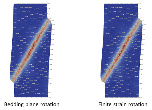
Defines the method for rotation of the material axis system (which is used for definition of orthotropic properties for example). Valid values are: • 0 - Standard finite strain theory • 1 - Bedding plane rotation method (default)
Note in the pictures below (in which arrows show direction of orthotropy) that bedding-plane rotation is more suitable for basin-scale geologic problems as rotation of material properties is less disturbed by distributed shear whereas for simulation of small-scale geomechanical test finite strain theory provides a more accurate representation of grain reorientation within the shear band.
|
| Average_pressure_flag Flag for average pressure formulation |
Usage |
||||
|
||||
Description |
||||
Defines whether or not the average pressure formulation is used for 2D triangular elements. Valid values are: • 0 - No average pressure formulation (Default: non-viscous material models) • 1 - Use average pressure formulation (Default: viscous material models, salt, Herschel-Bulkley).
The average pressure formulation smooths the effective mean stress field for 2-D triangles. It is advantageous for modelling viscous material with near zero yield stress as it alleviates volume locking. It is not suitable for elastic or elastoplastic materials with non-zero yield stress or constitutive models with pressure-sensitivity; e.g. SR3, SR4, Drucker-Prager and Cam Clay models.
Notes •The average pressure formulation is used by default if the viscoplastic salt or Herschel-Bulkley models are specified for an element group. |
| Average_pressure_factor Factor of averaged mean stress to be used in average pressure formulation |
Usage |
||||
|
||||
Description |
||||
The average pressure formulation smooths the effective mean stress field for 2-D triangles. It is advantageous for modelling viscous material with near zero yield stress as it alleviates volume locking. It is not suitable for elastic or elastoplastic materials with non-zero yield stress or constitutive models with pressure-sensitivity; e.g. SR3, SR4, Drucker-Prager and Cam Clay models. The default value of Average_pressure_factor = 0.01 (1%). Increasing the value leads to more stress smoothing and conversely reducing the value reduces stress smoothing.
|
| Average_pressure_frequency Number of mechanical steps between each average pressure smoothing update |
Usage |
||||
|
||||
Description |
||||
Number of mechanical steps between each average pressure smoothing update (default 1).
|
| Geometric_properties Geometric properties for group |
Usage |
|||||||||||||||
|
|||||||||||||||
Description |
|||||||||||||||
Geometric_properties allows constant geometric properties to be assigned to a group. Geometric properties are required for element types:
bar2d - 2-D Bar element •Location 1 - Area of bar
bar3d - 3-D Bar element •Location 1 - Area of bar
|
|||||||||||||||
| Contact_property_name Name of contact property group for group |
Usage |
||||
|
||||
Description |
||||
Assigns a contact property (by name) to the group. This may be used in cases in which contact properties should be representative of mixed formations (e.g. in cases where a fault lies between shale and sand layers).
|
| Kerogen_assignment Name of Kerogen property data |
Usage |
||||
|
||||
Description |
||||
Assigns a kerogen property (by name) to the group.
|
| Bulk_damping_model Model name for bulk damping |
Usage |
||||
|
||||
Description |
||||
The model number for bulk damping. Valid model numbers are: • "None" - No bulk damping (default) • "BulkViscosity" - Linear bulk viscosity model • "BulkStiffness" - Viscous damping based on the bulk stiffness
|
| Bulk_damping_parameter Bulk Damping Properties |
Usage |
||||
|
||||
Description |
||||
The bulk damping parameter is model dependent.
Model 1 - Bulk viscosity model The poroelastic parameter is the: • Location 1 - Bulk viscosity constant ( Qlin) (Default 0.5)
Model 2 - Viscous damping based on the bulk stiffness The poroelastic parameters is the: • Location 1 - Bulk stiffness factor ( Fbulk)
|
| Fracture_activation_flag Defines whether a fracture is active in the initial state on a group basis |
Usage |
||||
|
||||
Description |
||||
Flag to define whether a fracture is active in the initial state on a group basis. Valid values are:
• - Not assigned (default) • 0 - Inactive • 1 - Active • 2 - Completely inactive for a group (this may be used to prevent development of hydraulic fracture)
|

