Case 2 Extension With Rapid Sedimentation Rate
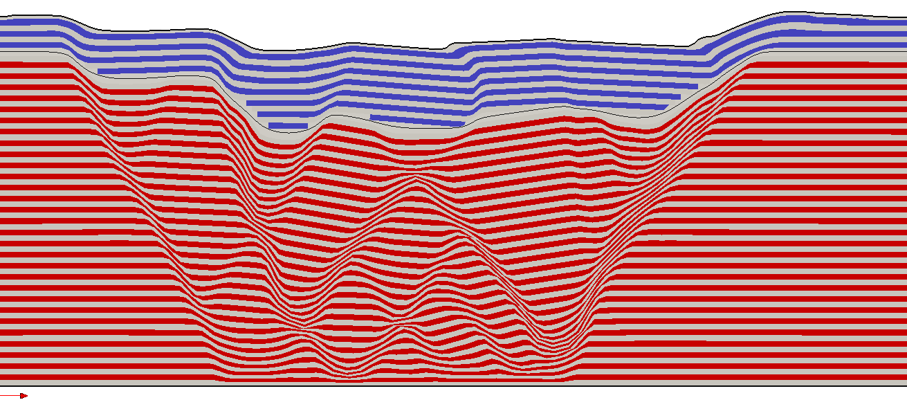
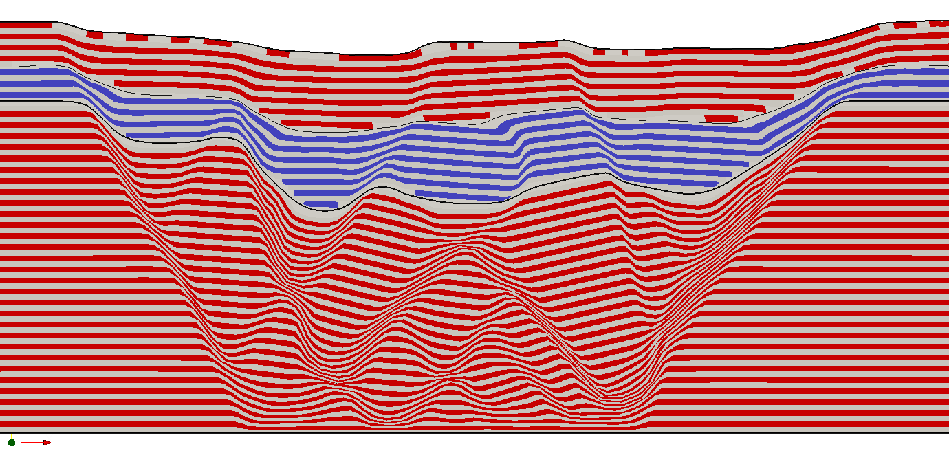
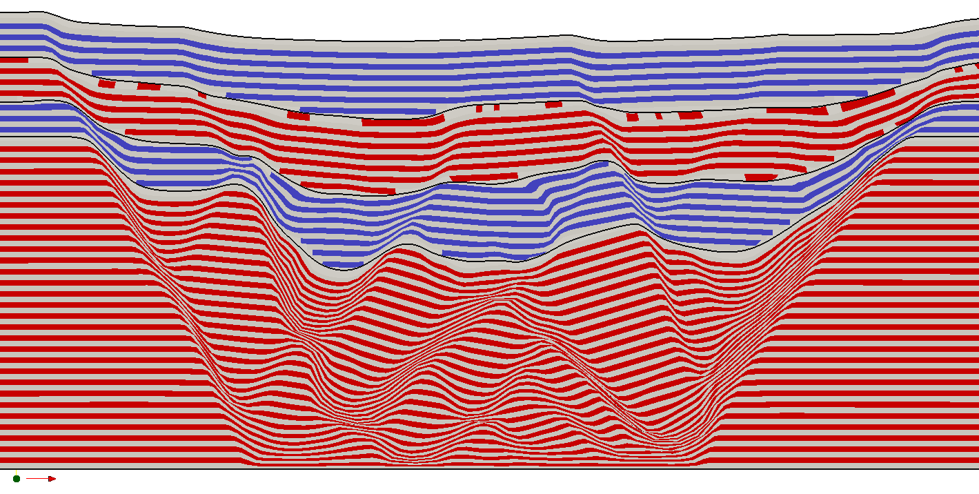
Sedimentation of additional sand is performed at time 3.0, 4.0, and 5.0 by defining a moving sedimentation surface and sedimentation data at these times.
Sedimentation_horizon
Data File |
|
* Sedimentation_horizon NUM=1 ! --------------------------------- Name "General" Facet_topology IDM=2 JDM=1 1 2 Coordinates IDM=2 JDM=2 0.0 25.0 200.0 25.0 Time_curve 1000 Displacement IDM=2 0.0 20.0
* Load_curve_data NUM=1000 ! --------------------------------- Time_curve IDM=2 1 6 Load_factor IDM=2 0 1
|
1Sedimentation horizon 1 is named "General" and defined by a single facet. 2The facet geometry is horizontal and has an initial elevation of 25mm; i.e. less than the height of the original sediment (30mm high). 3The horizon is defined as moving with a reference vertical displacement of 20mm and time curve 1000. 4Time curve 1000 defines that the sedimentation horizon moves at constant rate between time t=1.0 and t=6.0.
|
Sedimentation_data
Data File |
|
* Sedimentation_data ! --------------------------------- Stratigraphy_unit_name "Sand2" Sediment_horizon_name "General" Material_name "Sand_1" Duration 0.8
|
1Three Sedimentation_data keywords are defined at time t=3.0, t=4.0 and t=5.0. 2Each data structure defines: (a) The name of the new stratigraphy unit (b) The sedimentation horizon to be used (always "General") (c) The material properties to be assigned to the new unit (always "Sand_1") (d) The duration of the gravity initiation for the new layer (always 0.8)
|
The result files for the project are in directory: mech_003\exercises\Case 2\results. The contour plot for plastic strain show that three thinner layers of sediment are deposited, with all layers covering the complete model. The shear bands in the pre-kinematic sand layer propagate into the syn-kinematic layers with increasing extension.

Contours of Plastic Strain at Time t=6.0

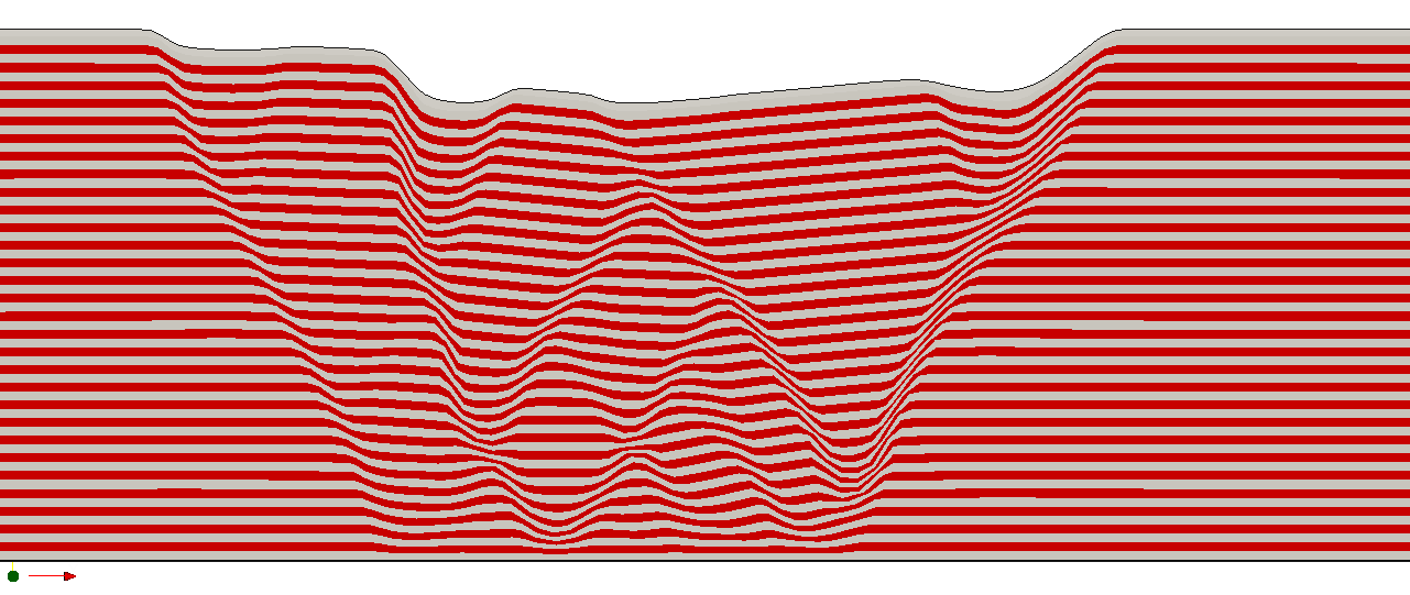
Configuration of Material Grid at Time t=3.0

Configuration of Material Grid at Time t=4.0

Configuration of Material Grid at Time t=5.0

Configuration of Material Grid at Time t=6.0
