Case 3 Refinement using Rate Error Indicators
Rate error indicators may be defined in the Adaptivity_set_data data structure to define the target element size based on the normalised rate of change of a state variable; e.g. the plastic strain rate. This is achieved by specifying a table of data where:
•Row 1: defines the value of the normalised state variable rate in ascending order.
•Row 2: defines the target element size corresponding to the state variable rate value.
The state variable rate is evaluated using the time averaged values the the previous and current error estimation check; i.e. in this problem this is the change in the state variable over a 250 steps. Normalisation of the rate simplifies the definition of the rate error data as the normalised rate lies in the range 0.0 to 1.0 for the majority of the domain, with higher values confined to regions of high deformation rate.
Data File |
|
||||||||||||||||||
* Adaptivity_set_data NUM=1 ! --------------------------------- Distortion_area_data IDM=1 15 Element_sizes IDM=2 /Max. Element Size/ 1.5 /Min. Element Size/ 0.50 Coarsening_type "P_strn" Coarsening_data IDM=3 JDM=2 /Plastic Strain/ 0.0 0.20 0.50 /Element Size/ 1.50 1.00 0.75 Rate_error_type "P_strn" Rate_error_data IDM=4 JDM=2 /Normalised Rate/ 0.0 0.1 0.25 0.5 /Element Size/ 1.5 1.2 0.60 0.50
|
The minimum element size is reduced from the Case 2 0.75 to 0.50 The coarsening type is defined on "P_strn" - plastic strain with the same table as Case 2; i.e.
The target element size for the rate error based on "P_strn" - plastic strain is defined by the table:
|
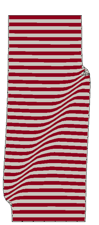
The result files for the project are in directory: mech_004\exercises\Case 3\results. The contour plots for plastic strain and plastic strain rate show that the rate error indicator further refines the mesh in the region of the shear band resulting in a tighter more refined shear band relative to Case 1 and Case 2 with plastic stain coarsening data. For this case a similar solution could be obtained just using mesh coarsening data by defining a smaller element size in the Coarsening_data. For general problems, however, rate error refinement has two advantages:
1The rate error is able to identify localised deformation earlier in the formation of a shear band, whereas Coarsening_data is based on the total accumulated value which is low in the early phase of localised deformation
2The rate error identifies localisations that are currently active, and consequently will not refine the mesh on localisations that become inactive reducing the total number of elements required.
Consequently the procedures are generally used together, with the rate error identifying regions of active high deformation rate, and Coarsening_data to prevent regions that have high strain, but are now inactive, becoming over-coarsened due to the current lack of activity.
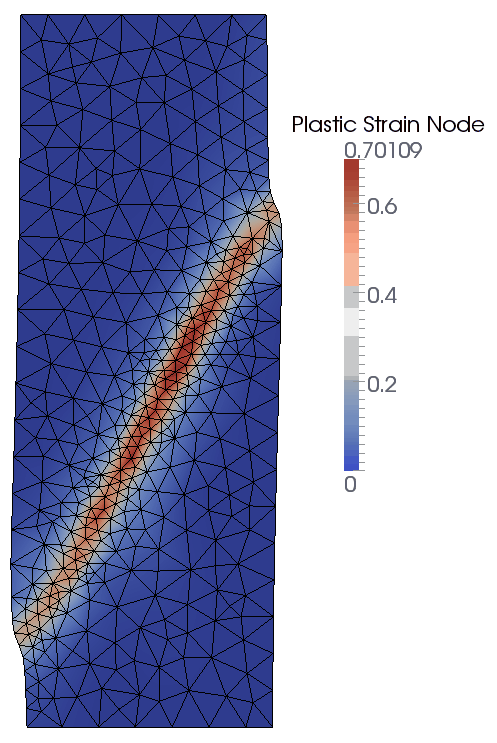
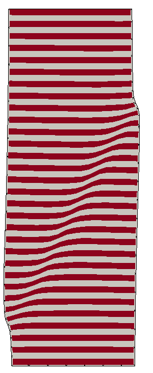
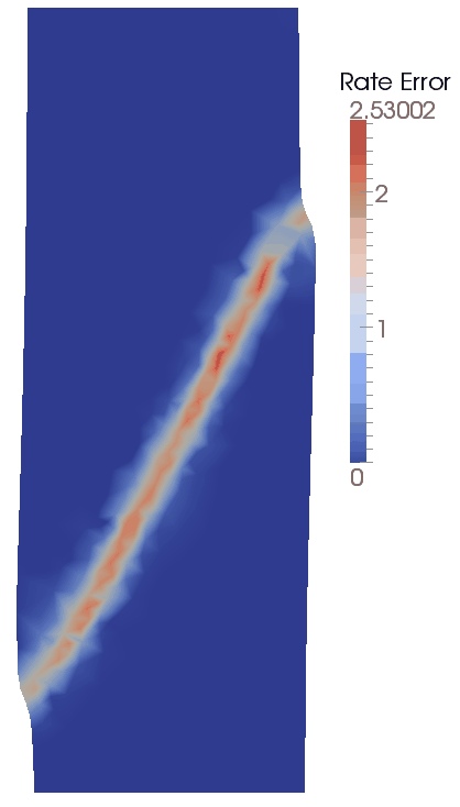
Configuration at Time t=0.5s
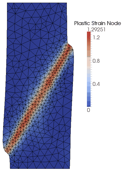
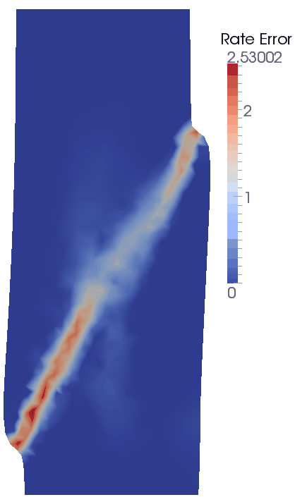
Configuration at Time t=1.0s
