Case 1B Plate With Hole (Quadratic Lines)
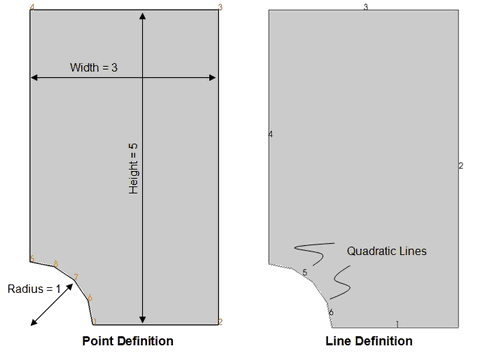
This example considers a plate with a hole. Quarter symmetry is used so that only one quarter of the plate is represented. The dimensions are; Half width = 3 , Half height = 5, Radius = 1. The geometry is defined by 8 points, with the circumference of the hole represented by two quadratic curves, each defined by three nodes.

Data File |
|
||||||||||||||||||||||||||||||||||||
! Quadratic Line Definition * Geometry_line NUM=5 line_type 2 points IDM=3 5 8 7
* Geometry_line NUM=6 line_type 2 points IDM=3 7 6 1
! Surface Definition * Geometry_surface NUM=1 lines IDM=6 1 2 3 4 5 6
|
Eight points are defined with coordinates:
Lines 1-4 are linear lines (type 1) defined by 2 nodes Lines 5 and 6 are quadratic (type=2) defined by 3 nodes The surface is defined by 6 lines |
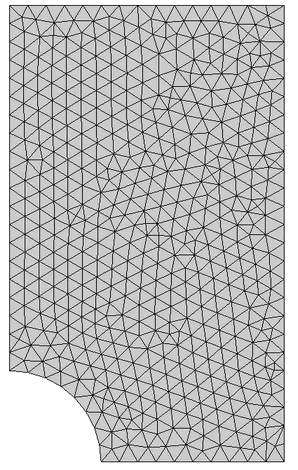
The generated mesh for a constant element size of 0.2 is shown below

Mesh for Constant Element Size = 0.2
The data and result files for the project are in directory: mesh_001\Exercises\Case 1B
