PFO_001 3 layer column

Contents
The present tutorial demonstrates ParaGeo-Pflotran-OGS coupling in a three layer column model geometry (overburden, reservoir, and underburden) used to simulate CO2 injection on a reservoir. Key aims for this tutorial are to:
•Demonstrate Pflotran-OGS grid data generation from a ParaGeo meshed geometry
•Discuss in detail typical Pflotran-OGS input data
•Demonstrate the coupling data set up (both ParaGeo and Pflotran-OGS data files)
•Demonstrate different flow modelling assumptions
•Demonstrate mapping for non-matching meshes
•Demonstrate output and post-process of ResInsight results
Model geometry
The dimensions of the geometry are shown in the figure below which consist of:
•Length in X-Y directions of 2000 m
•Reservoir Depth (measured at the top surface) of 1350 m
•Reservoir thickness of 50 m
•Depth of model base of 1500 m
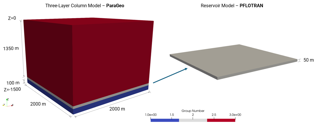
Geometry model dimensions
Note that:
•The simulations will assume quarter symmetry, where injection of CO2 will be performed on a corner of the reservoir.
•The flow model (Pflotran-OGS) will consider the reservoir formation only whereas the geomechanical model (ParaGeo) will include the three formations (underburden, reservoir and overburden).
•The overburden and underburden are assumed to have different porosities and permeabilities to the reservoir eventhough they will not be used in the flow simulations.
Simulation Cases
The present tutorial considers the simulation cases listed below. Note that the first case will be described in detail whereas in the remaining cases only the key data will be discussed.
Case01 Generation of Grid data
Case01 Injection of CO2 in a saline aquifer
Case02 Simulation of gas production followed by CO2 injection
Case03 Demonstration of mapping for non-matching meshes