Porous_flow_control_data
Data Structure: Porous_flow_control_data |
|
Description |
"Seepage Control Data" data structure |
Usage |
Porous_flow_control_data NUM=ival where ival is the data structure number |
Description |
Overview The Porous_flow_control_data structure defines solution algorithm, output and termination data for the current stage for the porous flow field. It must be defined for both porous flow only simulations and also for multi-field simulations where the porous flow field is active. The main classes of analysis are:
Linear steady State Analysis In this case a single solution step is performed with no iterations. Consequently time step and termination data are not required and the primary keywords required are: •Solution_algorithm = 1 •Output_time_plotfile = 1
Single-Field Multi-Step Analysis Multi-step analysis includes nonlinear static, linear transient and nonlinear transient cases. Linear Transient Analysis Linear transient analysis is performed with a constant time step for each control stage and no iterations. Time integration is performed using an implicit unconditionally-stable backward Euler algorithm. The primary datasets required are: •Solution_algorithm = 3 •Initial_time_step •Termination data via Maximum_number_time_steps and/or Termination_time •Output data to screen, plot file and restart file
Nonlinear Static or Transient Analysis Nonlinear Static or Transient Analysis may be performed using either a constant or variable time step for each control stage. They utilise a Newton-Raphson method for an iterative solution strategy. Time integration for the transient algorithm is performed using an implicit unconditionally-stable backward Euler algorithm. The primary datasets required are: •Solution_algorithm = 2 (nonlinear static) or 4 (nonlinear transient) •Initial_time_step •Termination data via Maximum_number_time_steps and/or Termination_time •Output data to screen, plot file and restart file •Data for variable time step control if required. Unless the target number of iterations is provided (via Target_number_iterations ), in this case a constant time step will be used.
The iteration control data, including the convergence tolerances, can generally be left using the default values. The variable time step algorithm chooses the time step based on the expression:
where Δtcurr is the current time step, Δtnext is the time step for the next step, Ntarget is the target number of iterations and Ncurr is the number of iterations required for the current step.
Coupled Multi-Field Analysis In a multi-field simulation the data required for time step, output and termination are specified on the mechanical control data structure Control_data. Consequently the only data required are: •Solution_algorithm = 2 (nonlinear static), 3 (linear transient) or 4 (nonlinear transient) •Data for convergence and iteration control if required.
Notes •Many of the parameters are set by default. The minimum data comprises the termination data •For single field analysis the no further data for the current stage is read subsequent to reading the Porous_flow_control_data structure. •One data structure is required for each analysis stage
Examples demonstrating the usage of Porous_flow_control_data include: •All porous flow examples |
| Control_title Name assigned to Control stage (Optional) |
Usage |
||||
|
||||
Description |
||||
Name assigned to the current control stage (maximum 64 characters)
|
| Solution_algorithm Solution algorithm for explicit field (Compulsory) |
Usage |
||||
|
||||
Description |
||||
Solution algorithm for the porous flow field • 1 - linear static • 2 - nonlinear static • 3 - linear transient • 4 - nonlinear transient (default)
Notes •Solution_algorithm must be set to 2, 3 or 4 for multi-field coupled examples
|
| Initial_time Initial time for the analysis (default 0.0) |
Usage |
||||
|
||||
Description |
||||
Specifies that the simulation starts from a specific reference time. Generally Initial_time is not specified and is set to 0.0 by default
|
| Initial_time_step Initial time step for control stage (Compulsory) |
Usage |
||||
|
||||
Description |
||||
Defines the time step length for first time step of the control stage. The initial time step length must always be specified. For the default constant time step case the time step remains equal to the initial time step.
|
| Time_step_growth Time step growth |
Usage |
||||
|
||||
Description |
||||
Defines the time step growth between successive increments in the mechanical field specified as a factor; i.e. Δtnext =fgrowthΔtcurr where fgrowth is the growth factor ( fgrowth > 1).
Generally the default value is adequate and this parameter does not need to be specified.
|
| Maximum_time_step_growth Maximum time step growth |
Usage |
||||
|
||||
Description |
||||
Maximum time step growth between successive increments specified as a factor; i.e. Δtnext ≤ fgrowthΔtcurr where fgrowth is the growth factor ( fgrowth > 1) with a default value of unlimited growth
|
| Minimum_time_step Minimum time step size (Optional) |
Usage |
||||
|
||||
Description |
||||
Defines the minimum time step size below which the analysis is terminated.
Notes •Minimum_time_step is only required if variable time step is used or if convergence problems which may result in time step cutting are likely. •The default value of for Minimum_time_step is 0.
|
| Maximum_time_step Maximum allowable time step (Optional) |
Usage |
||||
|
||||
Description |
||||
Defines the maximum allowable time step size.
Notes •Maximum_time_step is only required if variable time step is used. •Once the maximum time step is reached this value not be exceeded. •By default the maximum time step size is unbounded.
|
| Number_time_increments Number of time increments for the stage |
Usage |
||||
|
||||
Description |
||||
If Number_time_increments is specified then the initial time step is evaluated as the stage time divided by the number of time increments. •The default value of for Number_time_increments is unused.
|
| Termination_time Termination time for control (Compulsory if multi-step solution) |
Usage |
||||
|
||||
Description |
||||
Defines the termination time for the current control stage. This is the absolute termination time rather than the duration.
|
| Duration The duration for the control step |
Usage |
||||
|
||||
Description |
||||
Specifies the duration for the current control stage. If the duration is specified then the Termination time for the current control stage is automatically set to the current time + the duration
|
| Maximum_number_time_steps Maximum number of steps for control (Optional) |
Usage |
||||
|
||||
Description |
||||
Defines the maximum number of steps for the current control stage (Default: 1E8). If the maximum value is reached the simulation will be terminated.
|
| Maximum_number_iterations Maximum number of iterations for a time step (Optional) |
Usage |
||||
|
||||
Description |
||||
Defines the maximum number of iterations for a time step (Default: 15). If the maximum value is reached the simulation will be terminated.
|
| Target_number_iterations Target optimal number of iterations (Required for Variable time step) |
Usage |
||||
|
||||
Description |
||||
Defines the target optimal number of iterations. This parameter indicates that variable time step is required and also controls the time step size. The variable time step algorithm chooses the time step based on the expression:
where Δtcurr is the current time step, Δtnext is the time step for the next step, Ntarget is the target number of time steps and Ncurr is the number of time steps required for the current step.
|
| Pore_converge_tolerance Tolerance for pore pressure convergence (Optional) |
Usage |
||||
|
||||
Description |
||||
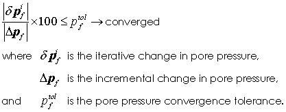
Defines the tolerance for pore pressure convergence using iterative and incremental values; i.e.
Notes •The default value is 0.01%
|
| Pore_total_tolerance Tolerance for pore pressure convergence using total values |
Usage |
||||
|
||||
Description |
||||
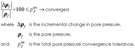
Defines the tolerance for pore pressure convergence using incremental and total values; i.e.
Notes •The default value is 0.0001%
|
| Residual_norm_tolerance Tolerance for residual convergence (Optional) |
Usage |
||||
|
||||
Description |
||||
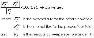
Tolerance for the residual flux is defined as:
Notes •The default value is 0.01%
|
| Max_number_timestep_cuts Max number time step cuts (Optional) |
Usage |
||||
|
||||
Description |
||||
Time step cutting can be used to repeat the current time step with a smaller step length if convergence with the current step length cannot be achieved. The maximum number of time step cuts specifies the number of times a time step can be cut before the analysis should be terminated. Each time step cut reduces the the time step length by 50%, so that the default value of max_number_timestep_cut of 3 terminates if convergence cannot be achieved with a time step of 12.5% of the initial value.
Notes •The default value of 3 is generally the best option. More than 3 time step cuts would imply a sudden large drop (ca. 90%) in the acceptable time step length
|
| Output_frequency_plotfile Output step frequency to plot file |
Usage |
||||
|
||||
Description |
||||
Number of time steps between output of results to the plot file. If a value of - 1 is specified then output will be performed at the end of the control stage. Note that if Output_frequency_plotfile is not defined no plot file will be output based on time steps/ increments nor at the end of stage.
|
| Output_time_plotfile Output time frequency to plot file |
Usage |
||||
|
||||
Description |
||||
Time between output of data to the plot file (Default 0.0 - No output based on time).
|
| Screen_message_frequency Output step frequency to screen |
Usage |
||||
|
||||
Description |
||||
Number of time steps between output of the log file data to the screen. If a value of - 1 is specified then output will be performed at the end of the control stage.
|
| Screen_message_time Output time frequency to screen |
Usage |
||||
|
||||
Description |
||||
Time between output of log data to the screen (Default 0.0 - No output based on time).
|
| Output_frequency_restart Output step frequency to restart file |
Usage |
||||
|
||||
Description |
||||
Number of time steps between output of results to the restart file named ModelName.rst . If a value of - 1 is specified then output will be performed at the end of the control stage to the file named ModelName_stage_No.rst where No is the stage number within the analysis. (Default Output_frequency_restart = - 1).
|
| Output_time_restart Output time frequency to restart file |
Usage |
||||
|
||||
Description |
||||
Time between output of data to the restart file named ModelName.rst (Default 0.0 - No output based on time)
|


