Case02 Usage of Coupled Freedoms
The data files for the project is in: SuEl_001\Case02\Step01\Data.
In Case01 the whole "Top" geometry set was retained. This means that all nodes from such geometry set were included in the reduced stiffness matrix. Nonetheless we may couple some or all degrees of freedom in the "Top" geometry set by using Couple_freedoms data structure and hence represent the behaviour of the Top geometry set with a single node. In this way the number of retained nodes to be incorporated into the super element matrix will decrease. This is demonstrated in the present case.
Here only the data relative to the "Create" step is discussed as the data to perform the simulation ("Use") and "Reflate" are identical to that of Case01.
Data File |
|
* Couple_freedoms NUM=1 ! --------------------------------- Geomechanical_codes IDM=3 0 0 1 Geometry_sets IDM=1 "Top"
|
1.Couple_freedoms is defined for the "Top" geometry set. 2.Only displacement in the Z direction will be coupled for all nodes within the "Top" geometry set. |
Data File |
|
* Super_element_control ! --------------------------------- Field "Gmech" Solution_type "Create" File_name "SuEl_001_Case02" Retained_couple_freedoms IDM=1 1 Retained_groups IDM=1 "Billet"
|
1.Retained_couple_freedoms keyword is specified in order to retain couple freedoms set number 1 defined in the data file. This will automatically create a single node that will represent the "Top" geometry set. |
Results
The results for the project are located in SuEl_001\Case02\Step01\Results and in SuEl_001\Case02\Step02\Results. Note that in the present case the displacement in the X and Y directions at the Top surface has not been constrained. A reference solution for the present case (which do not use the super element approach) is also provided.
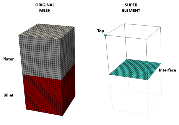
In the present case we have used Couple_freedoms for the top surface so that the boundary condition may be applied to a single node. Hence only this node plus all nodes connected to the Billet are retained in the super element (see the picture below). Consequently the number of nodes included into the super element matrix (output in SuEl_001_Case02.suelmat file) is decreased relative to Case01. This can be noted from the comparison of the super element matrix file sizes for Case01 (54.7 MB) and the present Case02 (13.7 MB). It should be noted that while in the present case that difference in file size may not be relevant, for large models involving millions of elements it may become important and hence usage of Couple_freedoms may be advantageous.
Image showing the original mesh (left) and the created super element with the retained freedoms in blue (right)
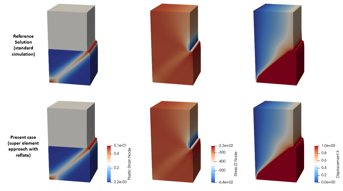
In the picture below the results from the reference solution are compared to the results using the super element approach after reflate of the super element. As can be seen results are identical in both cases. It can be noted that the reflated results show the correct displacement in X direction distribution in the top surface even though a single node has been used to apply the boundary condition at the top surface.
Results for the reference solution (top) compared to the ones obtained using the super element approach (bottom)
|


