Ex_011 Parameterised boundary
Preliminary Note: Usage of parameterised boundaries is compatible with Parallel simulations, with deposition and remeshing. Thus, such functionality is available for forward modeling over geological time scales. |
This tutorial example aims to demonstrate usage of Parameterised_boundary data, which is used in conjunction with Spatial_boundary to enable a distribution of displacements to be applied to a boundary as depicted in the figure below. To this end the same geometry from MEM_001 tutorial will be used.
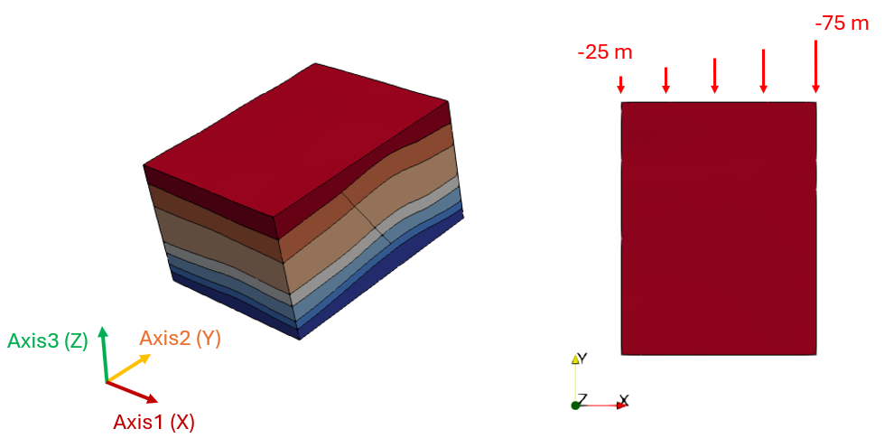
Geometry for all the cases with the 3 distribution axis defined (left). Example of displacement distribution applied to a boundary for Case01 (right)
The simulations will be performed using the implicit solver for the mechanical field and will encompass a gravity initialisation stage followed by a tectonic displacement stage. The data files for all the cases are provided in ParaGeo Examples\General Examples\Ex_011\Data with the results being provided in the corresponding \Results sub-folder.
It is noted that if the boundary displacements are not meant to be applied at the first simulation stage, a "bare" Parameterised_boundary data identifying the Geometry_set associated with the Parameterised_boundary must be defined in the first stage as shown below in the data taken from Case01.
Data File |
|
* Parameterised_boundary NUM=1 ! --------------------------------------- Geometry_set "North"
* Control_data ! ======================================= Control_title "init" (...)
* Spatial_boundary NUM=2 ! ---------------------------------------- Name "Para_bound" Boundary_type "Spatial_grid" Value_type "Absolute" Parameterised_boundaries IDM=1 1 Prescribed_components IDM=1 JDM=1 2
* Parameterised_boundary NUM=1 ! ---------------------------------------- Geometry_set "North" Distribution_axis 1 Prescribed_values IDM=2 -25 -75
* Control_data ! ======================================= Control_title "Tectonic" (...)
|
1.A "bare" Parameterised_boundary data associated to "North" boundary is defined in the initial stage.
2.In the second stage the displacements are being applied. Thus Parameterised_boundary and Spatial_boundary are defined with the appropriate data as required.
3.In Spatial_boundary we define:
i.Boundary_type must be set to Spatial_grid as internally ParaGeo will create a spatial grid with which the displacements will be mapped to the boundary nodes.
ii.In Parameterisend_boundaries keyword we define the list of ID numbers corresponding to the parametrised boundaries associated with the present Spatial_boundary
iii.In Prescribed_components we define which displacement components will be prescribed for each of the associated parametrised boundaries listed within the keyword Parameterisend_boundaries. Note that component numbers 1, 2 and 3 correspond to X, Y and Z respectively. Note that the the IDM dimension corresponds to the number of prescribed components whereas JDM dimension corresponds to the number of parametrised boundaries associated to the present Spatial_boundary .
4.In Parameterised_boundary we define:
i.The associated Geometry_set which in this case is "North"
ii.In Distribution_axis we define the number corresponding to the axis along which the displacements will be distributed. Axis numbers 1, 2 and 3 correspond to X, Y and Z directions respectively.
iii.The Prescribed_values are used to define the amount of displacement applied to from the minimum to the maximum coordinate of the specified Distribution_axis for the associated boundary Geometry_set (case with 2 Prescribed_values)
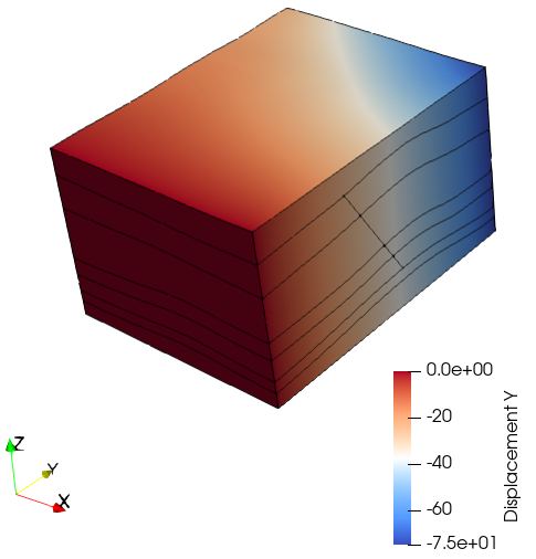
5.Thus, in the present example a linear distributions of displacements along the X axis is applied in the negative Y direction for the North boundary, ranging from a displacement of -25 m in X = 0 m to a displacement of -75 m at X=8000 m.
|
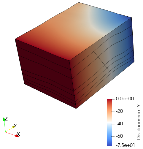
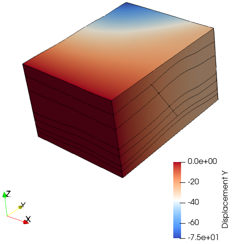
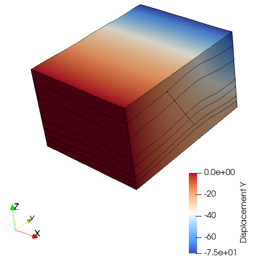
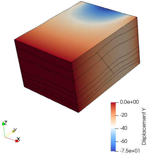
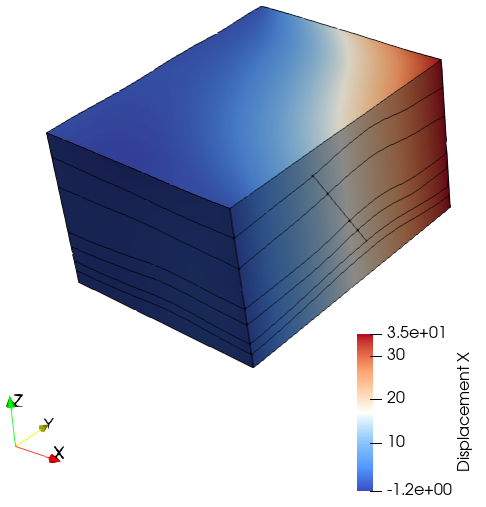
Below the displacement results for different data set ups corresponding to the different provided cases are shown.
Case01
Data File |
|
* Spatial_boundary NUM=2 ! ---------------------------------------- Name "Para_bound" Boundary_type "Spatial_grid" Value_type "Absolute" Parameterised_boundaries IDM=1 1 Prescribed_components IDM=1 JDM=1 2
* Parameterised_boundary NUM=1 ! ---------------------------------------- Geometry_set "North" Distribution_axis 1 Prescribed_values IDM=2 -25 -75
|
1.Case01 considers a linear distributions of displacements along the X axis applied in the negative Y direction for the North boundary, ranging from a displacement of -25 m in X = 0 m to a displacement of -75 m at X=8000 m.
|
Case01b
Data File |
|
* Spatial_boundary NUM=2 ! ---------------------------------------- Name "Para_bound" Boundary_type "Spatial_grid" Value_type "Absolute" Parameterised_boundaries IDM=1 1 Prescribed_components IDM=1 JDM=1 2
* Parameterised_boundary NUM=1 ! ---------------------------------------- Geometry_set "North" Distribution_axis 1 Prescribed_values IDM=2 -75 -25
|
1.Case01b considers a linear distribution of displacements along the X axis applied in the negative Y direction for the North boundary, ranging from a displacement of -75 m in X = 0 m to a displacement of -25 m at X=8000 m.
|
Case02
Data File |
|
* Spatial_boundary NUM=2 ! ---------------------------------------- Name "Para_bound" Boundary_type "Spatial_grid" Value_type "Absolute" Parameterised_boundaries IDM=1 1 Prescribed_components IDM=1 JDM=1 2
* Parameterised_boundary NUM=1 ! ---------------------------------------- Geometry_set "North" Distribution_axis 3 Prescribed_values IDM=2 -25 -75
|
1.Case02 considers a linear distribution of displacements along the Z axis (Distribution_axis 3) applied in the negative Y direction for the North boundary, ranging from a displacement of -25 m at the base to a displacement of -75 m at the top.
|
Case03
Case03 considers a quadratic distribution of displacements so that 3 prescribed values at the Minimum, Center and Maximum coordinates for the boundary are provided.
Data File |
|
* Spatial_boundary NUM=2 ! ---------------------------------------- Name "Para_bound" Boundary_type "Spatial_grid" Value_type "Absolute" Parameterised_boundaries IDM=1 1 Prescribed_components IDM=1 JDM=1 2
* Parameterised_boundary NUM=1 ! ---------------------------------------- Geometry_set "North" Distribution_axis 1 Prescribed_values IDM=3 -25 -75 -10
|
1.Case03 considers a quadratic distribution of displacements along the X axis applied in the negative Y direction for the North boundary according to the specified values.
|
Case04
Case04 considers two parameterised boundaries, one applying compressional displacements in the North as in all the previous cases and one applying a distributed extensional displacement in the X direction along the Y axis to the East boundary. Note that in this case each Parameterised_boundary is associated to a separate Spatial_boundary. In Case04b an alternative set up that yields identical results is demonstrated.
Data File |
|
* Spatial_boundary NUM=2 ! ---------------------------------------- Name "Para_bound_N" Boundary_type "Spatial_grid" Value_type "Absolute" Parameterised_boundaries IDM=1 1 Prescribed_components IDM=1 JDM=1 2 ! disp_y
* Parameterised_boundary NUM=1 ! ---------------------------------------- Geometry_set "North" Distribution_axis 1 Prescribed_values IDM=2 -25 -75
* Spatial_boundary NUM=3 ! ---------------------------------------- Name "Para_bound_E" Boundary_type "Spatial_grid" Value_type "Absolute" Parameterised_boundaries IDM=1 2 Prescribed_components IDM=1 JDM=1 1 ! disp_x
* Parameterised_boundary NUM=2 ! ---------------------------------------- Geometry_set "East" Distribution_axis 2 Prescribed_values IDM=2 0 35
|
1.Case04 considers two parameterised boundaries:
i.Parameterised_boundary NUM=1 is used to prescribe displacements in the Y direction (Prescribed component 2) along the X axis (Distribution_axis 1) to the North boundary
ii.Parameterised_boundary NUM=2 is used to prescribe displacements in the X direction (Prescribed component 1) along the Y axis (Distribution_axis 2) to the East boundary
|
Case04b
Case04b considers an alternative set up to achieve the same results as in Case04. In this case both parametersied boundaries are associated to the same Spatial_boundary.
Data File |
|
* Spatial_boundary NUM=2 ! ---------------------------------------- Name "Para_bound_N" Boundary_type "Spatial_grid" Value_type "Absolute" Parameterised_boundaries IDM=2 1 2 Prescribed_components IDM=1 JDM=1 2 ! disp_y 1 ! disp_x
* Parameterised_boundary NUM=1 ! ---------------------------------------- Geometry_set "North" Distribution_axis 1 Prescribed_values IDM=2 -25 -75
* Parameterised_boundary NUM=2 ! ---------------------------------------- Geometry_set "East" Distribution_axis 2 Prescribed_values IDM=2 0 35
|
1.Case04b considers two parameterised boundaries:
i.Parameterised_boundary NUM=1 is used to prescribe displacements in the Y direction (Prescribed component 2) along the X axis (Distribution_axis 1) to the North boundary
ii.Parameterised_boundary NUM=2 is used to prescribe displacements in the X direction (Prescribed component 1) along the Y axis (Distribution_axis 2) to the East boundary
2.A single is used in this case, yielding identical results to Case04.
|

