MEM_001 MEM Workflow
This tutorial example aims to demonstrate the MEM workflow in ParaGeo including model initialization using the implicit solver and well elements definition. Specific topics covered are:
1.Model initialization in multiple stages followed by production simulation
2.Explicit and Implicit initialization
3.Change from implicit to explicit simulation stages using restart files
4.Mechanical model set up for production simulation via prescribed spatial pore pressure
5.Hydro-Mechanical (HM) model set up for production/injection simulation via prescribed well element surface pressures
6.De-activation of porous flow shale groups for HM model
7.Implicit-implicit HM modelling with node-node contact algorithm
8.Mapping of previous simulation results to a spatial surface and output to a new plot file
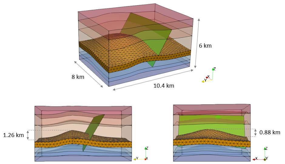
The model geometry is 8 km x 10.4 km x 6 km containing 7 formations which are assigned names Formation01 to Formation07 from oldest to youngest formation and where Formation04 is a Reservoir. The main structure consists of a two way anticline with a fault intersecting the southern limb. The top of the reservoir in the anticline crest is at c.a. 2.6 Km depth and it has a maximum relief of 1.26 km in the North-South direction and a maximum relief of 0.88 km in the East-West direction.

Model geometry from different perspectives
Formation04 is considered a reservoir with poroelastic properties whereas the rest of formations are considered shales with elastic properties. The fault is defined to obey a Mohr-Coulomb friction law according to a friction coefficient with no cohesion.
The simulation considers the following stages:
Initialization stages
•Stage 1 - Elastic gravity initialization
•Stage 2 - Tectonic displacement
•Stage 3 - Contact model release with displacement reinitialisation
•Stage 4 - Constitutive model release with displacement reinitialisation
Loading Stages
•Case01 and Case02: Geomechanical only - Production year 1 and year 2
•Case03: Hydro-Mechanical Coupling - Production 101 days
•Case04: Hydro-Mechanical Coupling - Combined production and injection - Production 101 days, 90 days injection
Four main cases are presented here:
Case 01:
Case 01 Base Case - Geomechanical (explicit) MEM simulation with production pore pressures via Spatial_grid data.
Case 01b Reservoir Spatial Table - As Case01 but with reservoir material Young's modulus as a function of porosity via Spatial_table data.
Case 02:
Case 02 Implicit Initialization - As Case01 but first two initialization stages solved using implicit solver and changed back to explicit solver using restart file for remaining two initialization stages and production stages.
Case 03:
Case 03a HM Coupled (High Perm Fault) - As Case01 but with fluid flow coupled to geomechanical analysis and the depletion of the reservoir layer from producer well 3 is modelled via Well_definition data using prescribed surface well pressure.
Case 03b HM Coupled (Low Perm Fault) - As Case03a but with low perm contact fluid flow at the fault.
Case 04:
Case 04 HM Coupled Producer and Injector Wells - As Case03a but with the inclusion of an injector well on the south-side of the anticline and utilising depth dependent normal and tangential contact flow models.
Case 04b HM Coupled with De-activated Porous Flow Groups - As Case04 but with porous flow field for shale formation groups de-activated.
Case 04c & 04d Implicit-Implicit HM Modelling - As Case04 and Case04b, respectively, but with implicit-implicit geomechanical-porous flow coupling and node-node contact algorithm.
