Case04b HM Coupled with De-activated Porous Flow Groups
The present case is a variation of the HM coupled producer and injector wells Case04 example. In this example, the porous flow field for the non-reservoir shale formation groups are de-activated - the initial spatial pore pressure distribution is applied but no porous flow coupling will be performed for these groups. All data files are identical to Case04 with the exception of Active_porous_flow_groups in Group_control_data in the MEM_001_Case04b.geometry file.
Note that the simulation run completes in 1.6 hrs on a 3.6 GHz AMD processor machine.
The data files for the project are in: MEM_001\Case04b\Data and the only files different from Case04 are:
•MEM_001_Case04b.geometry - Active_porous_flow_groups in Group_control_data data structure.
•MEM_001_Case04b.dat - to read in the above geometry file.
The following example must be undertaken beforehand:
1MEM_001 Case04 HM Coupled Producer and Injector Wells.
Data File (.geometry) |
|
* Group_control_data ! ---------------------------------------- Group_numbers IDM=7 1 2 3 4 5 6 7 Active_geomechanical_groups IDM=7 1 1 1 1 1 1 1 Active_porous_flow_groups IDM=7 0 0 0 1 0 0 0
|
1.In MEM_001_Case04b.geometry, de-activate the porous flow field in the shale element groups by setting Active_porous_flow_groups to 0 for all shale element groups. In other words, only the reservoir Formation04 group #4 is active in the porous flow field. |
Data File (.dat) |
|
! --------------------------------- * Include ! --------------------------------- Filename MEM_001_Case04b.geometry
|
1.Include MEM_001_Case04b.geometry in MEM_001_Case04b.dat data file.
|
Results
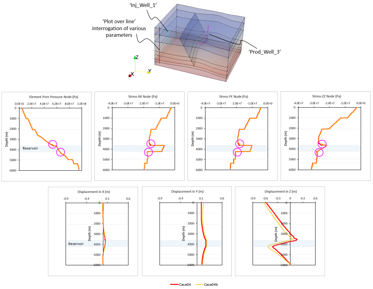
The results for the de-activated shale groups example (Case04b) are very similar to the all active groups example (Case04) and will not be presented in any detail. The figures below show a comparison of results at a section line at the injection well corner for all groups active (Case04) and with porous flow field for the non-reservoir shale formation groups de-activated (Case04b). Notice the main differences are at the top boundary of the reservoir layer (circled) with subtle differences in the pore pressures and stresses. When the porous flow is active in all the groups, there is resistance to flow from the adjacent shale groups whereas when the porous flow in the shale groups are de-activated, there is no resistance to flow at the boundaries with the adjacent shale groups. The differences in the pore pressures and stresses results in marginal increase in compaction for the de-activated group Case04b.

Comparison of results with all groups active (Case04) and with porous flow de-activated for shale groups (Case04b) for pore pressure, stresses and displacements.

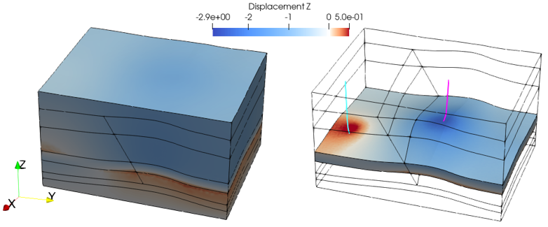
(a) Case04: All groups active

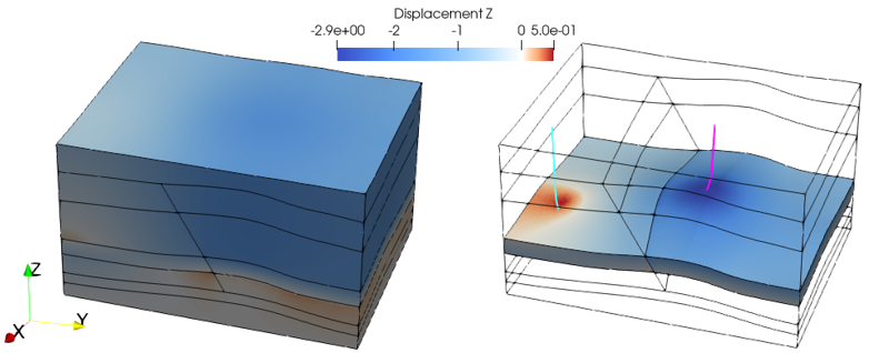
(b) Case04b: De-activated Shale porous flow groups
Comparison of displacements in Z with all groups active (Case04) and with porous flow de-activated for shale groups (Case04b).
