Case04c & 04d Implicit-Implicit HM Modelling
The present examples Case04c and Case04d are a variation of the HM coupled producer and injector wells Case04 and Case04b examples respectively. In these examples, both the geomechanical and porous flow fields are solved with an implicit solver (as opposed to the explicit solver) and with the node-node contact algorithm (as opposed to the node-facet contact algorithm).
The following examples are recommended to be undertaken beforehand:
1MEM_Case04 HM Coupled Producer and Injector Wells with all groups active. MEM_001 Case04c is the implicit variation of this example with the node-node contact algorithm.
2MEM_Case04b HM Coupled with De-activated Porous Flow Groups. MEM_001 Case04d is the implicit variation of this example with the node-node contact algorithm.
The data files for the project are in: MEM_001\Case04c\Data and MEM_001\Case04d\Data. Due to the similarity of the results, only the Case04d with the de-activated porous flow groups will be described here.
The Case04d data files are identical to Case04b with the exception of:
•MEM_001_Case04d.contact
•MEM_001_Case04d.dat
Notes on Initialization Stages:
•Gravity, Tectonic and Elastic Release initialization stages: In general, two to five implicit steps are sufficient for each of these stages. In this example, 5 steps have been adopted.
•Contact Release initialization stage: This stage generally require more implicit steps to achieve a converged solution. For this example, 20 steps have been adopted.
The following describes the differences between this implicitly solved geomechanical data file compared against the explicit geomechanical data file (MEM_001 Case04).
Data File (MEM_001_Case04d.contact) |
|
* Contact_global ! ---------------------------------------- Included_contact_sets IDM=1 "All" Algorithm 2 ! Node to Node Contact_flow_flag 1
* Contact_set NUM=1 ! ---------------------------------------- (...) Global_update_frequency 1 (...)
* Contact_property NUM=1 ! ---------------------------------------- (...) Adhesion_model 1 Adhesion_properties IDM=1 /Adhesion Penalty/ 2000.0E6 Compression_properties IDM=1 /Normal Penalty/ 2000.0E6 Tangential_model 2 Tangential_properties IDM=2 /Tangential Penalty/ 2000.0E6 /Friction coefficient/ 0.36 (...)
|
1.In the Contact_global data structure, the Algorithm keyword is set to 2 for node-node contact.
2.In the Contact_set data structure, the Global_update_frequency is set to 1 to update the contact global search at every increment.
3.In the Contact_property data structures for both "Fault_sand" and "Fault_shale": a.The normal penalty and tangential penalty are set to 2E9 Pa and the friction coefficient set to 0.36. b.Adhesion contact is utilized with Adhesion_model keyword set to 1 for elastic fully bonded adhesion model. The adhesion penalty value in Adhesion_properties keyword is set same as the normal penalty value, i.e. 2E9 Pa.
|
Data File (MEM_001_Case04d.dat) |
|
! --------------------------------- * Include ! --------------------------------- Filename MEM_001_Case04d.contact
! Damping_global_data data structure removed
! History_global data structure for energies, etc. removed
! ------------------------------------------------------------------- ! Gravity Initialization Stage 1 ! Tectonic Initialization Stage 2 ! Elastic Release Initialization Stage 4 ! -------------------------------------------------------------------
* Control_data ! --------------------------------- (...) Solution_algorithm 7 Duration 1.0 Initial_time_increment 0.2 ! 5 steps Displacement_norm_tolerance 0.01 Residual_norm_tolerance 0.01 Minimum_time_increment 1.0E-4 (...) Screen_message_frequency 1
! -------------------------------------------- ! Contact Release Initialization Stage 3 ! --------------------------------------------
* Control_data ! --------------------------------- (...) Solution_algorithm 7 Duration 1.0 Initial_time_increment 0.05 ! 20 steps Displacement_norm_tolerance 0.01 Residual_norm_tolerance 0.01 Minimum_time_increment 1.0E-4 (...) Screen_message_frequency 1
! -------------------------------------------- ! Flow Stages ! --------------------------------------------
* Control_data ! --------------------------------- (...) Solution_algorithm 7 (...) Displacement_norm_tolerance 0.01 Residual_norm_tolerance 0.01 Minimum_time_increment 1.0E-4 (...)
|
1.Include MEM_001_Case04d.contact file with contents as described above.
2.Damping_global_data and History_global data structures can be removed as we are solving with an implicit geomechanical steady state solver.
3.The solution Control_data for all stages is defined to be solved with the implicit nonlinear steady state solver, i.e. : a.Solution_algorithm = 7 b.Displacement_norm_tolerance = 0.01 c.Residual_norm_tolerance = 0.01 d.Minimum_time_increment = 1.0E-4
e.The initial time increment defined for each of the stages are different depending on the stage analysis involved: i.For each of the gravity stage 1, tectonic stage 2 and elastic release stage 4 initializations, 5 solution steps have been adopted, i.e. Initial_time_increment = 0.2 (stage duration = 1.0).
ii.For the contact release stage 3 initialization, more steps are required for a converged solution. To this end, twenty steps have been adopted, i.e. Initial_time_increment = 0.05 (stage duration=1.0).
iii.For the depletion and injection flow stages, the same number defined for the porous flow increments in the explicit geomechanical example (MEM_001 Case04b) will be used.
Notes: •The solution convergence are defined by the % allowable displacement and residual convergence tolerance values defined in Displacement_norm_tolerance and Residual_norm_tolerance keywords. •The Minimum_time_increment keyword defines the allowable minimum time increment for solution time cutting when non-convergence occurs before the analysis is terminated. This prevents continuation of the analysis with unrealistically small time increments. |
Results
The results for the project are located in MEM_001\Case04d\Results. In this directory the spreadsheet 00_MEM_001_Case04d_Results.xlsx contains all the processed history results output from the simulation. Minimal results for the implicit-implicit HM (Case04d) will be presented here as they are very similar to that presented for the explicit-explicit HM (Case04b) results. However, as expected, due to the higher friction coefficient of 0.36 used in this example there is less contact nonlinear slip than in Case04b (with friction of 0.2), and the overall subsidence in the model and on the top surface is reduced. Note that for these MEM examples, no slip occurs with a realistic friction coefficient value of 0.6, thus a reduced friction coefficient was defined to demonstrate simulations with contact slip.
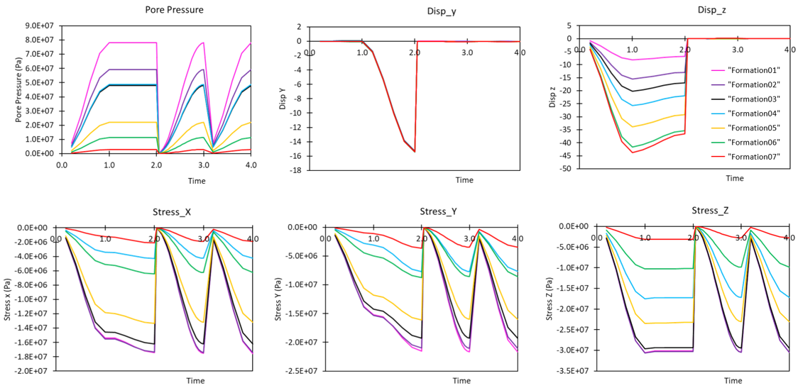
The figures below show the evolution of the different variables at the history monitoring points during the four stages of initialization: gravity stage 1 (time=0 to 1), tectonic stage 2 (time=1 to 2), contact release stage 3 (time=2 to 3) and elastic release stage 4 (time=3 to 4). These compare well with the explicit Case04b despite using significantly less time steps to solve.

Evolution of properties during initialization stages.
The plot on the left below show the contact plastic slip at the end of the simulation with friction of 0.36. As can be seen, the slip is localised in the reservoir layer where the high overpressure leads to relatively low contact normal effective stresses and hence relatively high ratios of contact tangential stress to contact normal effective stress. The two graphical plots below show the stress-state of the fault hanging wall contact nodes before and after the contact release initialization stages.

Contact plastic slip at the end of the simulation with friction of 0.36 and plots of stress-state of the Fault_hgw contact nodes before and after the contact release initialization stages
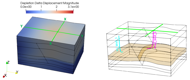
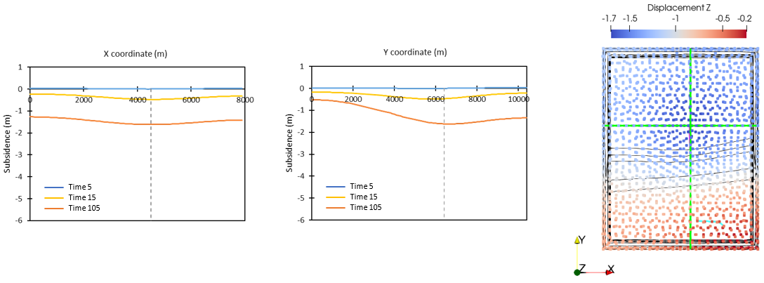
The figures below show the distribution of change of displacement in the model at the end of the simulation and the subsidence on the top surface and at various times along the two history section line sets (green lines) on the top surface.

(a) Change in displacement at end of simulation and locations of producer and injector wells

(b) Subsidence on top surface
Distribution of change in displacement and top surface subsidence at the history section lines "SubsidenceX" and "SubsidenceY" (green lines)
The figures below show the pore pressure, change in vertical stress and vertical displacements in the reservoir layer. Locations of producer and injector wells are incorporated in the figures for reference.

Pore pressure, change in vertical stress and vertical displacements in the reservoir layer. Reference locations of producer well 3 (pink) and injector well 1 (cyan) are also shown.
