Case02 Spatial Distribution of Facies
The present case will build from Case01 so that the same workflow using membrane elements and couple freedoms on boundaries will be followed. The user is assumed to have reviewed such case before undertaking the present one. The aim here is learning how to define a spatial distribution of facies and assign it to the model mesh to be used in both, restoration and forward simulations; with the facies distribution being imported from Zmaps.
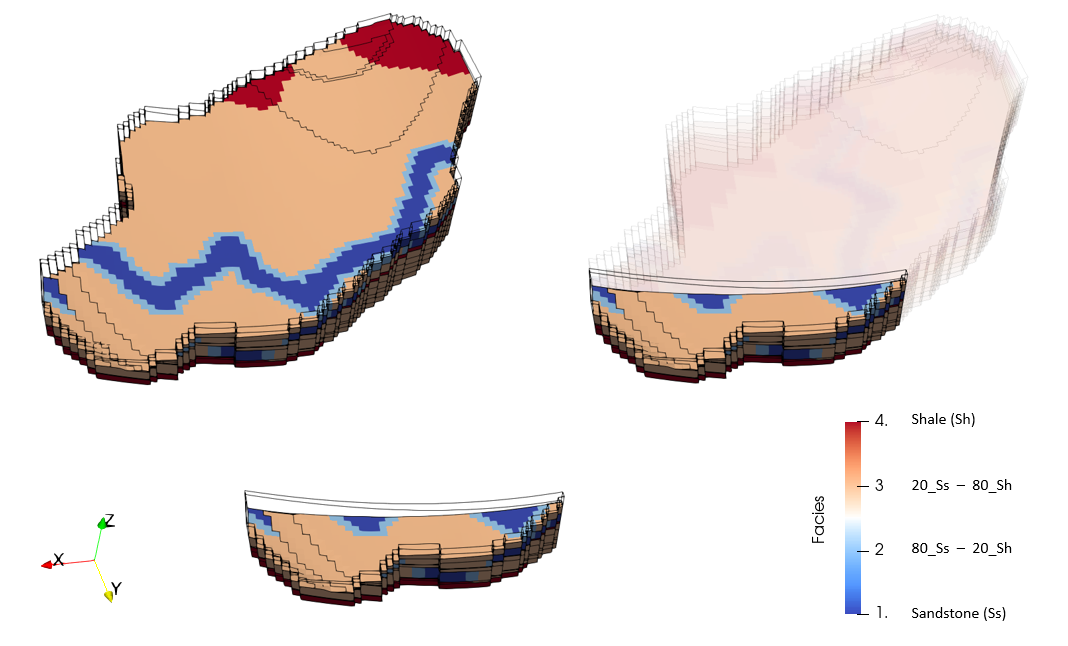
Usage of Facies in ParaGeo allows to consider different evolutionary material properties within the same group/formation which is often required in large scale problems both, during restoration and forward simulation. In the present tutorial 4 Facies are going to be considered: Sandstone, Shale and two different Sandstone-Shale mixtures. The picture below shows the distribution of facies in Formation08 imported from the Zmaps for both, the full model grid and the submodel considered in this tutorial (same submodel as in Case01)

View of the facies distribution in Formation08 for the full model and the submodel considered in this tutorial (Formations 09 and 10 are hidden). V.E. = 3
The workflow steps that will be followed in the present case are:
1.Zmap import including the import of facies Zmaps
2.Geometry create (conversion from the .inp generated from Zmaps to ParaGeo geometry)
3.Boundary extraction (step required for usage of couple freedoms on the boundary as demonstrated in Case01)
4.Restoration accounting for spatially distributed facies
5.Boundary extraction (2) to identify the boundary nodes to enable boundary displacement assignment for the forward simulation
6.Forward simulation accounting for sedimentation of spatially distributed facies (with the distribution for each formation obtained from restoration)
The key differences relative to Case01 for considering spatial distribution of facies are basically in extra data definition required in steps 1, 4 and 6.
