Case01 Membrane elements and boundary coupled freedoms
In the present case you are going to learn how to:
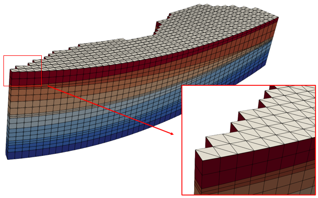
1.Use membrane elements in restoration to achieve bed length preservation. This is achieved by inserting a group of membrane elements which is attached to the corresponding top surface in each restoration stage. Such group of membrane elements is defined with a relatively high stiffness (user input) so that when translation / back-stripping of the top surface to the restoration surface is performed those elements hinder compression in the horizontal direction.

View of the model with the group of membrane elements on the top surface. Note that membrane elements are triangles.
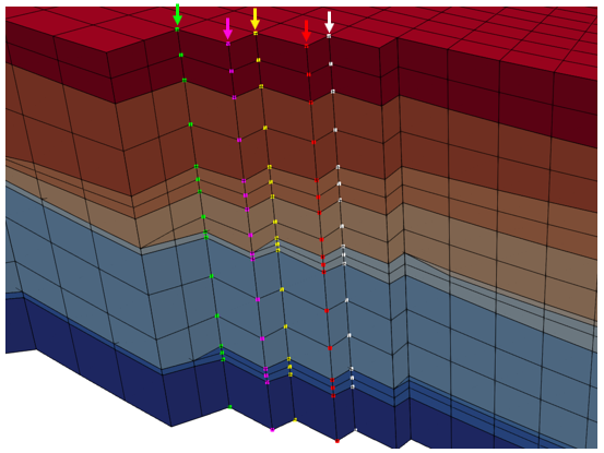
2.Define couple freedoms for boundaries on a column of nodes basis in order to prevent overturning of the elements during restoration. This means that during restoration the boundaries will remain vertical as the boundary nodes within a given column will have the same displacement in X and Y directions, controlled by the corresponding node on the top surface. This is required specially in cases involving membrane elements in restoration where the stiff membranes tend to result in element overturning due to the stiffness contrast. Avoiding element overturning is crucial to ensure that the forward simulation can be performed as overturned elements on the boundaries result in lack of vertical direction support in the overturned nodes, leading to boundary failure and termination of the simulation.

View of 5 columns of boundary nodes highlighted in different colours. The arrows on the top indicate the master node controlling the displacement in X and Y direction for each column of nodes.
The functionality described above will be demonstrated by going through the complete restoration - forward simulation workflow. Note that usage of the membrane elements only requires additional data in Restoration_data data structure but usage of the couple freedoms constrain on a column of nodes basis requires to modify the workflow relative to the tutorial case Geol_002. The present workflow then involves:
1.Zmap Import: Similar to the way it was performed in Geol_002 but incorporating additional data in order to output a .spat file containing a Spatial_grid with the requested output properties (in the present case will be I, J, K numbers for each cell, which is required to generate data for the couple freedoms constrain).
2.Geometry create: Workflow step identical to Geol_002. We just need to run the .inp file generated during the Zmap import in order to generate the geometry (.geo) file for the model domain.
3.Boundary extraction: In the present case identification and extraction of the boundary nodes is required to be performed prior to the restoration. During this workflow step geometry sets for the complete side boundary and for each individual node column in the boundary will be generated. This will be required for the application of the couple freedoms constrain during restoration.
4.Restoration: Additional keywords in Restoration_data are required for both; apply the couple freedoms constrain and to use membrane elements to approach bed length preservation.
5.Boundary extraction (2): Identification of the boundary nodes for the initial formation during forward simulation (final restored formation)
6.Forward simulation: No additional data is required for this workflow step compared to tutorial case Geol_002 but it will be briefly discussed for the sake of completeness.
