Step06 Forward Simulation
The data files for forward simulation are in: Geol_002b\Case03\06_Forward_sim\Data. Most of the files are identical to those in Case02 with the only difference being the extra stages for deposition of the eroded formation and its subsequent erosion included in the main data file and the corresponding displacement grid (.spat) files. It should be noted that the eroded formation does not have facies distribution obtained from restoration (as it is not explicitly modelled nor imported from Zmap) so that it can either:
1.Be assumed a single material/facies for the entire formation
2.Be assumed the same facies distribution as another formation (and hence the same facies grid may be assigned during its deposition)
3.The facies distribution grid may be defined manually
In the present case it is assumed that the eroded formation has the same facies distribution as the previous deposited formation (formation07). Below there is a description of the data within Geol_002b_Case03_fsim.dat file required to model the deposition and subsequent erosion of the eroded layer. The remaining data is not discussed here.
Forward simulation datafile
The present case comprises 12 stages with the sequence being as follows:
1.Geostatic stage with gravity initialisation and boundary displacements for creating the accommodation space between top surface and sedimentation horizon for deposition of formation02 (reversal of displacements during flattening of formation01 during restoration simulation) 2.Deposition of formation02 and boundary displacements to create the accommodation space for deposition of formation03 3.Deposition of formation03 and boundary displacements to create the accommodation space for deposition of formation04 4.Deposition of formation04 and boundary displacements to create the accommodation space for deposition of formation05 5.Deposition of formation05 and boundary displacements to create the accommodation space for deposition of formation06 6.Deposition of formation06 and boundary displacements to create the accommodation space for deposition of formation07 7.Deposition of formation07 and boundary displacements to create the accommodation space for deposition of the eroded formation 8.Deposition of the eroded formation and boundary displacements to expose the eroded formation above the sedimentation horizon (representing an erosion datum) 9.Removal/erosion of the eroded formation and boundary displacements to create the accommodation space for deposition of formation8 10.Deposition of formation08 and boundary displacements to create the accommodation space for deposition of formation09 11.Deposition of formation09 and boundary displacements to create the accommodation space for deposition of formation10 12.Deposition of formation10 and boundary displacements to create the present day topographic relief
Note that in all cases the sedimentation horizon corresponds to the flat restoration surface defined in Geol_002b_Case02_RestSurf01.dat file. Below a summary of the stage sequence and the key data for deposition and erosion of the eroded formation is discussed. Note that the remaining data will not be discussed here.
|
Results
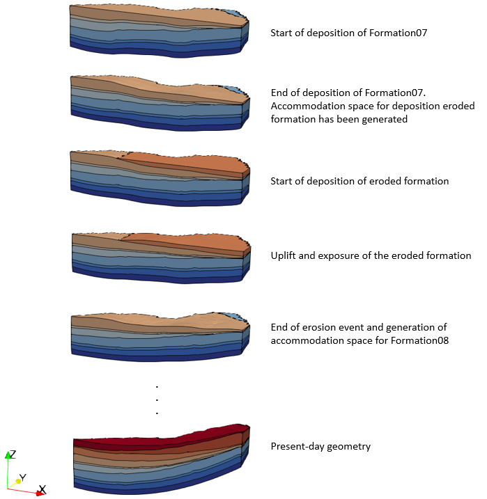
The results for the present workflow steps are provided in Geol_002b\Case03\06_Forward_sim\Results. Note that only a selection of the results is provided. In the figure bellow a detail of the modelled sequence for the eroded layer is shown. Thanks to the boundary conditions chosen during restoration, its derived displacements used to drive the boundary kinematics in the forward model we have been able to account for:
1.Generation of the accommodation space for deposition of the eroded formation 2.Uplift of the eroded formation so that it is exposed to erosion 3.Erode the formation and continue with the depositional sequence
Detail of the modelled sequence of deposition, uplift and erosion of the eroded layer. V.E. = 3
|

