GeomSect_001 Case4 Vertical plane non-parallel to XYZ coordinate system planes
The data file for this exercise is located in GeomSect_001/Exercices/Case4/Data. Look for ! TODO text in the datafile and follow the instructions.
In this example the section plane is rotated to perform a vertical section in a plane non-parallel to any of the ZX nor YZ planes. This is performed by defining a Coordinate_system defining the rotation.
In the International Society of Biomechanics web page an Excel Spreadsheet developed by Neil Crawford to calculate direction cosines for a X, Y, Z sequential 3D rotation can be downloaded. The instructions are included in the spreadsheet. Note that rotation should be performed using the tilt-twist input in the spreadsheet following the sequence:
1Define the sequential rotation in the input cells (B3 to B5)
2Look at the tilt-twist values provided in cells M3 to M5
3Change the input of the B3 to B5 for the tilt-twist values
4Copy the resulting direction cosines matrix in cells Q20 to S22
Data File |
|
* Coordinate_system NUM=1 ! --------------------------------- Direction_cosines IDM=3 JDM=3 0.9397 0.3420 0.0000 0.0000 0.0000 1.0000 0.3420 -0.9397 0.0000
* Geometry_section_surface ! --------------------------------- Section_type "XY_local" Generation_type "Section" Reference_location IDM=3 4250.0 1000.0 2000.0 Coordinate_system 1 Output_level 3 Groups IDM=4 "formation0" "formation1" "formation2" "formation3"
|
1A coordinate system to describe the rotation for sectioning is defined. In the present case the direction cosines correspond to a sequential rotation of: a.-90º along X axis b.0º along Y axis c.20º along Z axis d.Note that the final input in cells (B3, B4, B5) for the til-twist method has been (-90, -20, 0). 2Section_type is set to "XY_local" (flat and initially parallel to XY plane). 3Generation_type is set to "Section" (a .geo file containing the sectioned geometry and a datafile will be generated). 4Reference location is defined to be at the center of the geometry. 5Coordinate system 1 is assigned to the sectioning in order to rotate the section. |
Results
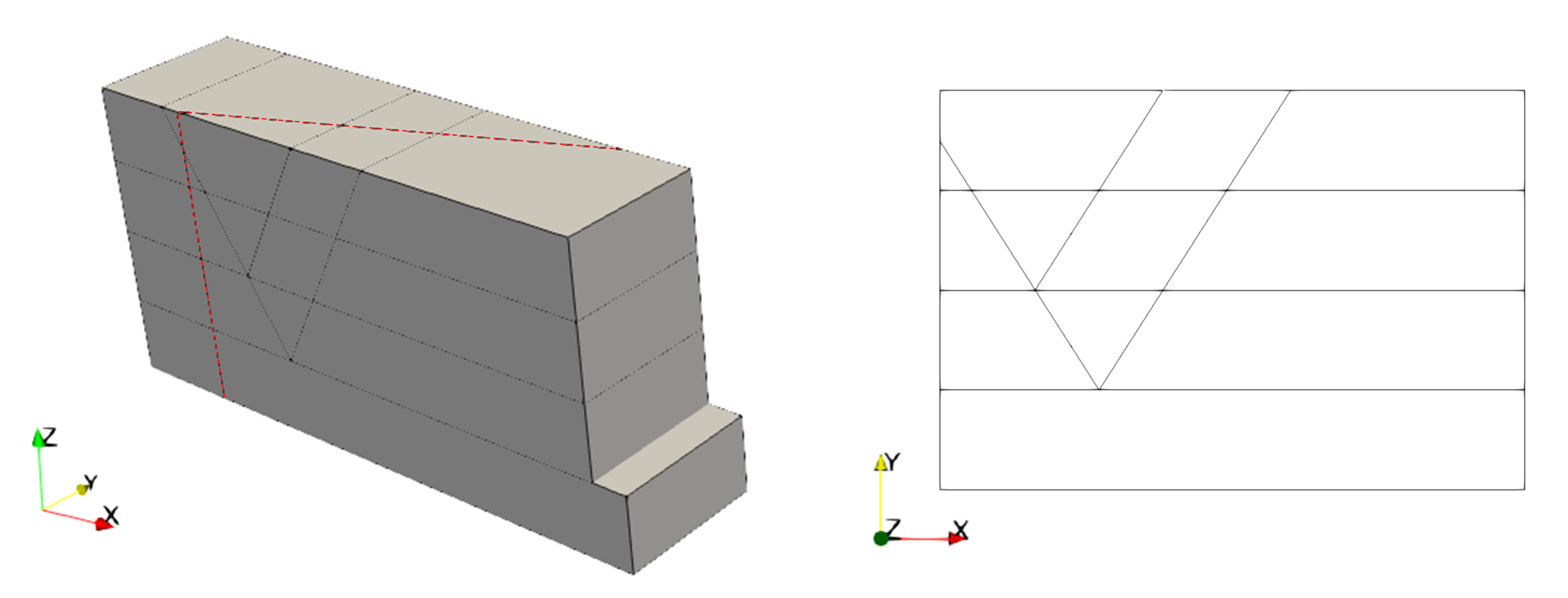
The result files for the project are in directory: GeomSect_001\Case4\Results. Note that the output section 2D geometry is oriented within plane XY as 2D problems in ParaGeo must be oriented in that plane.
3D geometry showing the section plane (left). Sectioned geometry (right)
|

