Case 2a and 2b Simulations with two fracture sets
The present examples assume that the user has undertaken Case1a and Case1b first.
Case2a and Case2b are poroelastic and poro-elasto-plastic simulations respectively very similar to cases 1a and 1b respectively with the following differences:
1.Lower matrix permeability is considered
2.An additional set of vertical fractures perpendicular to X axis is considered (see the figure below). The spacing for this fracture set is 5 cm.
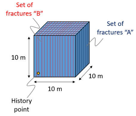
Schematic of model geometry
The initial data files for the project are: IX_003\Case2\Data\IX_003_Case2a.dat and IX_003_Case2b.dat
Material_data
Data File |
|
|||||||||||||||||||||||||||
* Material_data NUM=1 ! --------------------------------- Material_name "Reservoir" Grain_stiffness 30000E6
(...)
Permeability_vs_porosity IDM=21 JDM=2 /"Porosity"/ 0.01 0.02 ... 0.50 /"Perm. mD"/ 0.0029 0.0228 ... 356.9271 Biot_type 1 Biot_constant 1.0 Fluid_saturation 1.0 Singlephase_fluid_name Water Fracture_set_names IDM=2 "Type_A" "Type_B"
* Fracture_data NUM=2 ! --------------------------------- Name "Type_B" Propagation_model_name PreExist Fracture_spacing 0.050 Coordinate_system_name TypeB_fracture Normal_stiffness_model Bandis Normal_stiffness_properties IDM=3 /Joint Stiffness/ 4000E6 /Initial Aperture/ 0.0005 /Maximum Joint Stiffness/ 100000E6 Normal_strength_model Elastic Conductivity_model_name FracPermPorosity Conductivity_properties IDM=10 JDM=2 ! /"Aperture"/ 0.00005 0.00010 ... 0.00050 /"Porosity"/ 0.001 0.002 ... 0.01 /"Perm. mD"/ 0.020 0.160 ... 20.000 Flow_model_name SimpleHydro
* Coordinate_system NUM=2 ! ---------------------------------- Name TypeB_fracture ! YZ Plane Direction_cosines IDM=3 JDM=3 0.000 1.000 0.000 0.000 0.000 1.000 1.000 0.000 0.000
|
1.Most material properties are identical to cases 1a and 1b (for poroelastic and poro-elasto-plastic simulations respectively). Thus only the differences are discussed here. 2.Matrix porosity-permeability relationship is different than that for cases 1a and 1b (in cases 2a and 2b matrix permeability is lower for a given porosity than that for cases 1a an 1b). 3.In addition to the fracture set "Type_A" defined for cases 1a and 1b, an additional set of fractures named "Type_B" is assigned to the material. 4.The differences between the properties for the two set of fractures are summarized in the following table:
|
Results
The result files for the project are in directory: IX_003\Case2\Results
Two cases (poroelastic and case with SR4 plasticity) with two sets of fractures have been run. The fundamental differences between the poroelastic and plastic cases have been discussed in Case1b results section. Hence here the main focus will be on discussing the behaviour of the two fracture sets.
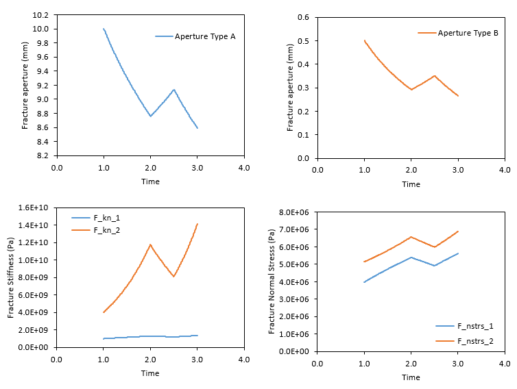
In the figures below the evolution of the fracture aperture, stiffness and normal stress for the two fracture sets resulting from the poroelastic simulation are shown. It can be seen that:
1.There is less change in the fracture aperture for Type B fractures (normal to X axis) than for Type A fractures (normal to Y axis). This is due to the fact that the spacing for Type B fracture (5 cm) is lower than that of Type A fractures (30 cm). This means that for the same amount of horizontal strain there will be more fractures accommodating displacement for the Type B fracture set (and hence less closure for each individual fracture).
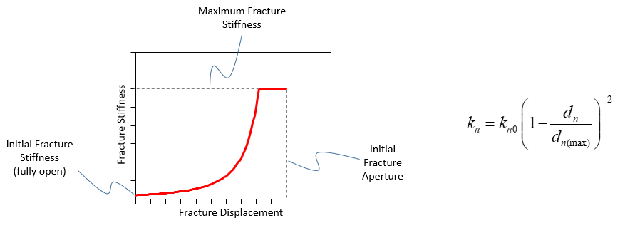
2.The total fracture stiffness and the change in fracture stiffness for Type B fractures is larger that that of Type A fractures. This is due to: 1) The initial stiffness for Type B fractures is 4 times larger than that for type A fractures and 2) the aperture of Type B fractures is very small compared to the aperture of Type A fractures and this results that even for a smaller change in aperture, the change in stiffness is greater as the fractures are much closer to achieve full closure (note that the fracture stiffness increases with fracture displacement according to the Bandis formulation, see the picture below).
3.The fracture normal stress is larger for Type B fractures than for Type A fractures.
Comparison of the evolution of fracture properties for the two fracture sets (poroelastic case)
Example of the evolution of fracture stiffness as a function of fracture displacement as modelled by the Bandis model implemented in ParaGeo
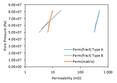
In the figure below there is a comparison of the evolution of permeabilities for the matrix and the two fracture sets as a function of the pore pressure. It can be seen that:
1.Permeability for Type A fractures is larger than that for Type B fractures as input in the data.
2.Type B fracture permeability is of the same order as matrix permeability.
3.When pore pressure decreases below c.a. 66·106 Pa the Type B fracture permeability gets lower than the matrix permeability.
Evolution of matrix and fracture permeabilities as a function of pore pressure
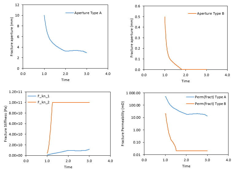
In the figure below the evolution of fracture aperture, fracture stiffness and fracture permeability for the two fracture sets in the case considering SR4 plasticity is shown. It can be seen that:
1.As expected the fracture displacements are larger than for the case considering poroelasticity with no plasticity (i.e. compare the two top figures below with the two top figures from the first figure set in the present result section).
2.The Type B fractures have achieved full closure during the first stage of pore pressure drop (t=1.0 to t=2.0 days). Consequently fracture stiffness has reached the maximum cutoff value input in the data and the minimum permeability value of 0.02 mD.
Evolution of fracture properties for the case considering SR4 plasticity
|

