Case 1C Plate With Hole (Quadratic Lines with Mesh Refinement)
This example extends example Case 1B by refining the mesh on the quadratic lines. This is achieved by assigning a target element size to these lines. Target mesh sizes can be assigned to any geometry entity and are used to construct target mesh size distribution at the underlying geometry points. Mesh generation is then performed using the point-wise distribution. The point-wise value is evaluated by processing all the entities with specified values in the geometry hierarchy order i.e. volume assignments are processed first, these are overwritten by surface assignments, which are over-written by line assignments, which are overwritten by point assignments.
Mesh refinement may also be controlled by using mesh regions (Mesh_region) (see exercise Case 1D).
Data File |
|
* Unstructured_mesh_data ! --------------------------------- Default_element_size 0.4 Element_size_bounds IDM=2 /Max. Element Size/ 0.4 /Min. Element Size/ 0.4 Lines IDM=2 5 6 Line_element_size IDM=2 0.2 0.2
|
The default mesh size is increased to 0.4 but a mesh size of 0.2 is assigned to the quadratic lines 5 and 6 |
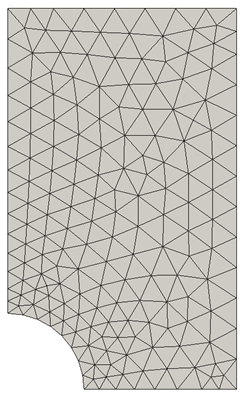
The generated mesh is shown below

Mesh for Default Mesh Size = 0.4 and Element Size = 0.2 on Quadratic Lines
The data and result files for the project are in directory: mesh_001\Exercises\Case 1C
