Case02 Parameter with local expression

Contents
In this example, we simplify Case01 setup by forgoing the use of parameter Block_height. Instead, we replace this parameter name by directly using the expression Height+1 in the Nodal_data data structure. Note that the parameter names and expressions are case-insensitive. Also, underscore is used to represent space within parameter names and expressions.
Basic Set Up: Data File Description
The data file for the project is in : ParDef_001\Case02\Data. The key data structures relevant to the definition of parameter definition for the current example are: •Parameter_definition to define parameter names and values. •Global_loads to replace load value with parameter name "Load". •Nodal_data to replace coordinate points with parameter names "Length", "Height", "Block_width", and local expression "Height+1".
|
Parameter_definition •Defines parameter names and parameter values
|
Global_loads •Defines the surface load value through parameter name
|
Nodal_data •Defines coordinate points through parameter name
|
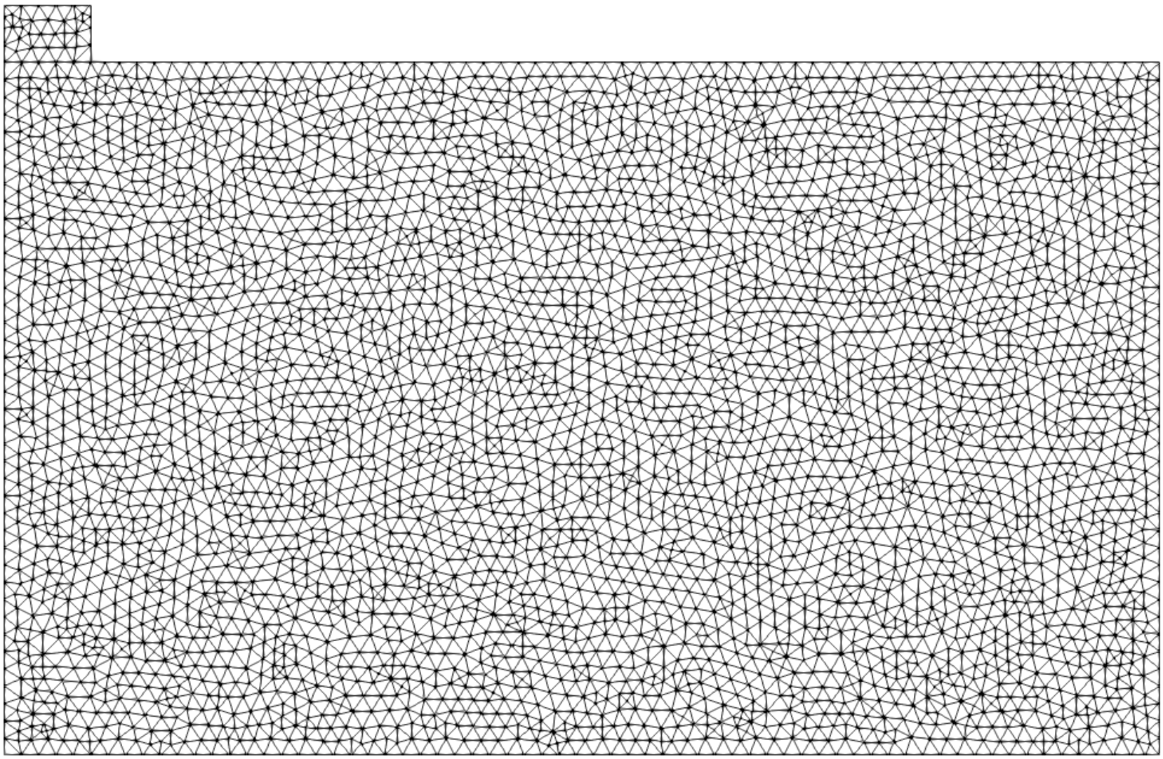
The following mesh model should be identical to other case models presented in ParDef_001 example.
|