Overview
Restoration Overview
Geological restoration is a technique that consists of progressively undeforming the present day structural state of a target geological structure or system of structures to its pre-deformation state. Hence restoration simulates the evolution of the target geological system backwards in time (from present to the past). This technique was originally developed to validate structural interpretations from seismic sections, or more precisely, to invalidate them; in the sense that if a given structural interpretation is not restorable or leads to unrealistic/incompatible scenarios, then the interpretation may be deemed not valid.
During restoration the events of sedimentation, burial, compaction, folding and fault displacement are reversed. This process is performed sequentially in several restoration stages where one formation (or stratigraphic layer) is considered at a time. One of the main principles of restoration is assuming a restoration datum / restoration surface that is representative of the paleo sedimentation surface (which may be flat or not) for the current top stratigraphy layer. Thus in every restoration stage the following sequence of operations is generally performed:
1.Remove the top-most formation / stratigraphy layer. This represents the reversal of sedimentation.
2.Back-strip the new top surface to the restoration datum (current top surface is displaced to match the restoration datum). During this procedure, in addition to reverse the burial, folds will be unfolded and some fault offset will be recovered as a consequence of the displacement applied to the top surface.
3.Perform a decompaction operation according to compaction curves assigned to the different formations and based on the updated depth.
Then the simulation will go to the next restoration stage and the sequence will be repeated for the next formation / stratigraphy layer. This may be done until the last formation is back-stripped to the restoration surface or until the paleo-time of interest. It should be noted that:
1.In the very first restoration stage only back-strip operation is generally performed.
2.There may be restorations that do not consider decompaction at all.

Schematic representation of a restoration stage
There are different restoration methodologies which are based on different underlying assumptions; namely:
1.Geometrically-based restorations. Some software adopting this technique allow to split the section to be restored in blocks delimited by faults that can then be moved and deformed one by one in a puzzle-fashion. Hence this technique only provides the structural configuration at the end of each restoration stage (intermediate states are not computed). Area (2D) and volume (3D) preservation is adopted as a proxy for solid mass conservation. Several deformation algorithms may be considered to compute the valid undeformed block states such as vertical/inclined shear, flexural slip, trishear, etc. Note that also some assumptions may be adopted for the different stratigraphy horizons during back-stripping (e.g. bed-length preservation).
2.Kinetic restorations. Similar concept to the geometrically-based restorations but the restoration model is always connected (not split in blocks in a puzzle fashion) so that the evolution is simulated in relatively small time increments thus capturing the deformation pathways. Same principles of area/volume preservation are adopted as a proxy for solid mass conservation and the same deformation algorithms previously mentioned may be invoked to resolve the undeformation of the geological structures.
3.Geomechanical-based restorations. This restoration technique adopts the Finite Element Method (FEM) by which the behaviour of the sediments is modelled via constitutive models so that the deformation pathways are a result of the constitutive response of the materials to the imposed boundary conditions. The boundary conditions consist in the already mentioned back-strip of the top surface to the restoration surface and a "pin" location (a line in 2D; a line or a surface in 3D) to which normal displacements constraints are imposed in order to "anchor" the model and resolve the underformation relative to the pinned location. It should be noted that area/volume preservation is not imposed but rather the method directly honours mass preservation. Usually the sediments are considered to behave in an elastic manner to approach brittle behaviour with faults being represented by frictionless contact surfaces but constant volume plasticity models may be also used to enable undeformation of structures originated by ductile deformation. It should be noted that although this technique provides output of stresses resulting from the occurring strains, the magnitude of those is generally not physically meaningful.
Restoration in ParaGeo
ParaGeo features include the possibility to perform geomechanical-based restorations analysis. The restoration surface is defined via a part geometry (part line in 2D or part surface in 3D) which may have an arbitrary shape. During back-stripping several assumptions may be adopted for the top surface, encompassing free-horizontal displacement (resulting from the constitutive response of the sediment to the imposed vertical displacement to match the restoration surface), bed-length preservation (full prescribed displacement) or a force based bed-length constrain that allows to consider intermediate scenarios between the two already mentioned.
Generally the rheology of the sediments in geomechanical-based restorations is modelled via isotropic elasticity characterized by Young modulus and Poisson's ratio properties although some authors have used transverse isotropic elasticity to approach bedding plane slip (e.g. Durand-Riard et al. 2013). In ParaGeo you can use isotropic, transverse isotropic or orthotropic elasticity, Von Mises plasticity or Hill orthotropic plasticity model to simulate the rheology of the sediments during restoration. There is also available a bedding plane slip model that can be used in conjunction to any of the already mentioned constitutive models by which slip is controlled by a maximum shear stress criterion at every node of the domain creating continuum distributed planes of weakness.
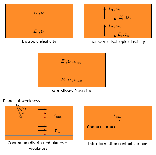
Schematic examples of models available in ParaGeo to represent sediment behaviour during restoration.
In ParaGeo the relative timing of back-stripping (and the consequent deformation) and decompaction may be controlled via usage of independent Time_curve data structures, thus adding flexibility. It should be noted that classical decompaction models consider compaction as a vertical phenomena resulting from burial and the weight of the overlying sediment thus neglecting any non-vertical compaction/stretch resulting from tectonic deformation (see the strains in the 3D fold model below). In ParaGeo decompaction may be performed adopting one of the two available models:
1.Vertical decompaction model according to assigned porosity-depth curves. This approach is similar to the decompaction models in classical restoration methods with the difference that the porosity-depth curve is defined by pair of points and is not tied to any known compaction model (e.g. Athy, Easysoil, etc.) thus enabling to be consistent with any available well data (e.g. an under-compacted porosity trend for overpressured sediments).
2.Directional decompaction model by which strain component maps are input by the user via Spatial_grid data and the decompaction is performed to reverse those input strains. This therefore enables to account for spatially distributed non-vertical compaction.
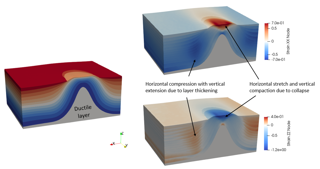
3D ParaGeo ductile fold model highlighting non-vertical deformation components resulting from tectonic deformation
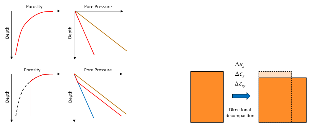
Schematic compaction curves for normally pressured and overpressured sediments (left). Schematic of directional decompaction (right).
Integrating Restoration and Forward Simulations in ParaGeo
Geomechanical models account for the evolution of the 3D stress tensor and account for the sophisticated physics involved in basin formation including sedimentation, compaction, burial, structural development, diagenesis, etc. One key feature of geomechanical models is that they are free in nature in the sense that only boundary conditions are prescribed whereas the interior of the model evolves freely as a result of the sediments constitutive response to the boundary conditions (as opposed to classical basin modelling techniques where the geometry evolution is fully prescribed and the geomechanics, if present, are simplified). Consequently the final geometry obtained from a geomechanical simulation is predicted. Hence geomechanical models may be used to provide a better understanding of the evolution of geological systems specially in complex scenarios, e.g.:
1.Near and sub-salt reservoirs where principal stresses are rotated and strain may be non-vertical.
2.Basins with important tectonic deformation such as fold-and-thrust belts in which the most compressive principal stress may be horizontal.
3.Unconventional resources where a detailed geomechanical description may be beneficial to improve predictions of natural hydraulic fracturing and subsequent hydrocarbon migration.
4.Regional-scale structural evolution over geological time frames in which geomechanical models may provide insight into the formation of geological structures and conditions required for a given type of structure to develop (see the as an example the predicted structural evolution for a gravity spreading system in a progradation delta due to overpressure in the figure below).
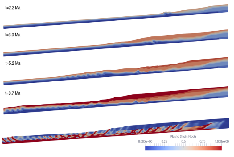
ParaGeo evolutionary coupled hydro-mechanical modelling of gravity spreading in progradation delta due to overpressure (F.P. Tan, 2020)
In some applications the target goal may be to develop a forward geomechanical model for a given structure (or system of structures) of interest and being able to reproduce it as accurately as possible. It should be noted however that even at sandbox scale, where boundary conditions and evolution are known and material properties may be measured in lab experiments, it is often difficult to match an observed present day structure. At basin scale uncertainty is much higher, where only present day state may be known to some extent whereas boundary conditions, structural evolution or fault topology at paleo times are not known. In that regard output results from restoration may be used to add additional constraints to forward simulations, namely:
1.The final restored geometry after the end of last restoration stage provides the initial geometry for a forward model.
2.The kinematics derived from restoration provide insight on the structural evolution and hence may help to constrain the boundary conditions for the forward model.
In ParaGeo a workflow that integrates restoration and forward simulations is available. In such workflow the restoration output results at the end of each restoration stage are processed and used by the code to automatically generate data input for the forward model concerning:
1.Initial geometry derived from the final restored geometry.
2.Prescribed boundary kinematics for the base and sides of the model derived by reversing the restoration boundary displacements.
3.Sedimentation data for each formation. The sedimentation horizon is coincident with the corresponding restoration surface and the accommodation space for the new sediment between the sedimentation horizon and the top surface is created from the boundary displacements and the deformation of the model.
4.Fault propagation pathways derived from fault topology at the end of each restoration stage.
Such additional constraints derived from restoration facilitate a forward simulation that can reproduce a target structure of interest with the maximum possible accuracy. A good example of that is the usage of the fault topology from restoration in order to define fault propagation pathways during forward simulation that may be difficult to reproduce otherwise.
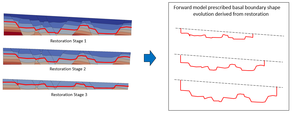
Example of basal and side boundary conditions for a forward model derived from restoration. Note that the base of the model may be arbitrarily chosen from any of the horizons in the restoration model. Obtained from Crook et al. (2018)

Example of sedimentation and fault propagation sequence in a forward model derived from restoration
Iterative workflow for improving predictions from Restorations and Forward Simulations in ParaGeo
As already mentioned, restoration is a technique that enables to investigate past deformation states and gain insight on the structural evolution of a target geological system. The assumptions adopted however are not based on physics but are rather a pragmatic approach to enable the application of such technique. In addition classic restorations neglect some physical processes that may be crucial for the development of given geological structures (e.g. ductile tectonic compaction). On the other hand forward geomechanical models are more sophisticated and richer in physics, encompassing constitutive models to simulate sediment rheology that are able to capture elastic and plastic compaction, brittle failure, viscoplasticity, diagenesis, evolution of stiffness and strength with consolidation, etc. Due to the very different assumptions between those two techniques it is expected that the final geometry predicted by a forward geomechanical model (with constraints derived from restoration) will differ to some degree with the field observations. In addition the errors in the restoration boundary kinematics due to the simplified assumptions are carried to the forward model (e.g. the lack of recovery of ductile tectonic compaction during restoration results in underestimation of the shortening in the basin which in turns results in an underestimation of the predicted thrust fault slip during the forward simulation; see Butlers and Paton, 2010).
Here we suggest that the restoration/forward simulation integrated workflow may be used to iteratively improve either or both, restorations and forward simulations (see the workflow chart below). For example we may take advantage of the results obtained from a forward simulation to correct some assumptions in a second iteration of the restoration and consequently obtain better boundary conditions for the forward model (following the example of the underprediction of fault slip in the thrust fault we may decide to either add more shortening during the forward model or to use the directional decompaction model in ParaGeo to recover some non-vertical compaction during the restoration and increase the recovered shortening which in turn will lead to more shortening being applied during the forward simulation). Note that several iterations may be performed until we are satisfied with the forward simulation predictions.
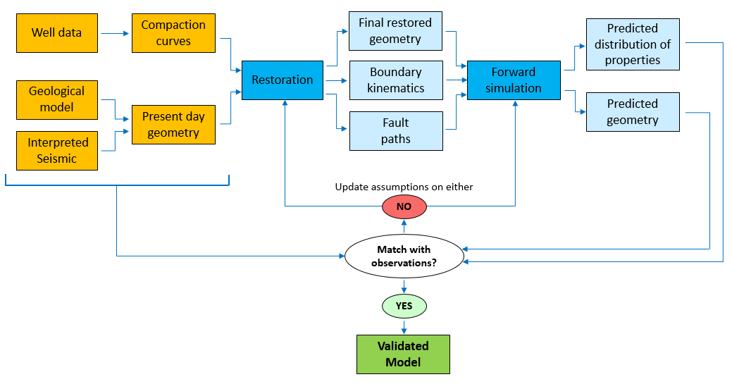
Workflow chart for iteratively improving restorations and / or forward simulations
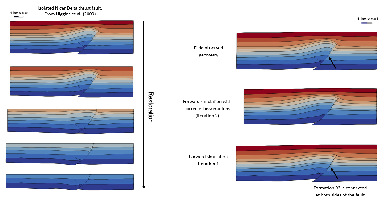
Example of corrected assumptions during forward simulation in order to improve prediction of fault slip and fold crest layer thicknesses
References
Butlers R.W.H., Paton D.A. (2010). Evaluating lateral compaction in deepwater fold and thrust belts: How much are we missing from “nature’s sandbox”? GSA Today 20, 3, 4–10.
Crook, A.J.L., Obradors-Prats, J., Somer, D., Peric, D., Lovely, P., Kacewicz, M. (2018). Towards an integrated restoration/forward geomechanical modelling workflow for basin evolution prediction. Oil & Gas Science and Technology - Rev. IFP Energies nouvelles 73, 18, 1-19.
Durand-Riard P., Guzofski C., Caumon G., Titeux M. (2012). Handling natural complexity in three-dimensional geomechanical restoration, with application to the recent evolution of the outer fold and thrust belt, deep-water Niger Delta. AAPG Bulletin 97, 1, 87–102.
Higgins S., Clarke B., Davies R.J., Cartwright J. (2009) Internal geometry and growth history of thrust-related anticline in a deep water fold belt. J. Struct. Geol. 31, 12, pp. 1597–1611
Tan, F.P. (2020). Constitutive modelling for sedimentary evolution at basin scale. PhD Thesis, Swansea University, U.K.
