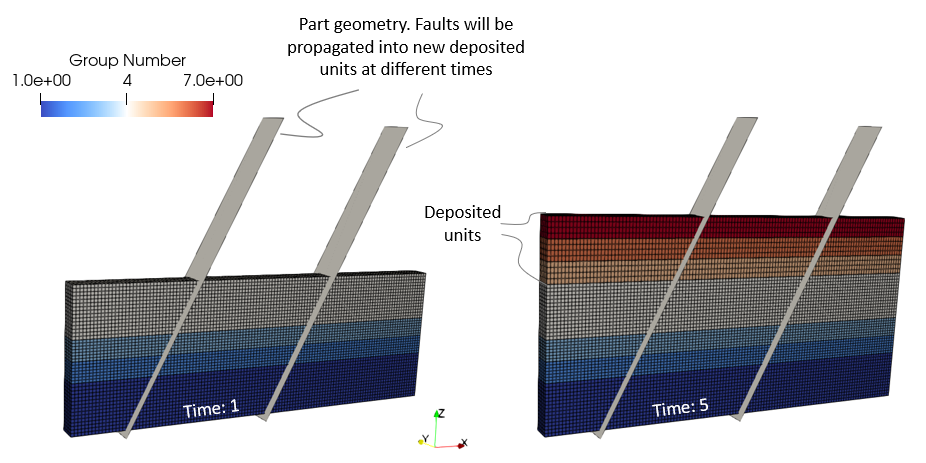
The present example considers a layered model with deposition of 3 additional formations to demonstrate how to set up fault propagation considering multiple faults that propagate at different times. Additionally different properties for each fault have been considered. For the sake of simplicity the model considers a fully fixed geometry (displacements are constrained in all directions) and consequently the data setup may not be representative of a physically realistic scenario (e.g. in the present case only few mechanical time steps are used). In addition no relevant flow conditions are imposed as the objective is to demonstrate how to set up fault propagation with multiple faults.
|
Initial and final model mesh and geometries
|
Considering continuum fault flow model requires assignment of the corresponding Fracture_data into the material(s). If no fracture data is assigned to a given material then the continuum fault model will have no effect in such material even if the fault is prescribed.
Material_data
Data File
|
|
* Material_data NUM=1
Name "Sand"
(...)
Permeability_type 2
Permeability_vs_porosity IDM=19 JDM=2
0.010 ... 0.800
2.0E-20 ... 7.3271E-12
Fracture_set_names IDM=2
"Fract01"
"Fract02"
* Material_data NUM=2
Name "Shale"
(...)
Permeability_type 2
Permeability_vs_porosity IDM=19 JDM=2
0.010 ... 0.800
1.0E-22 ... 1.84E-17
Fracture_set_names IDM=2
"Fract01"
"Fract02"
|
1The present case considers two materials and two different fractures. Consequently the two fractures named "Fract01" and "Fract02" are assigned to both materials to enable prescribed faults in the ParaGeo groups defined with such materials. 2The present case considers a isotropic permeability that is a function of porosity. Note that it is compulsory to define an isotropic perm law (either constant or a function of porosity) in order to use the continuum fault model (transverse isotropic or orthotropic perm is not allowed). |
Part geometry
Data File
|
|
* Part_geometry_set NUM=1
Name "Fault01_part"
Part_type "Fault"
Part_surfaces IDM=1
1
* Part_surface NUM=1
Facets IDM=3 JDM=2
1 2 3
1 3 4
* Part_nodal_data NUM=1
Nodes IDM=4
1 2 3 4
Coordinates IDM=3 JDM=4
1000 -200 -100
1000 600 -100
4000 600 5900
4000 -200 5900
* Part_geometry_set NUM=2
Name "Fault02_part"
Part_type "Fault"
Part_surfaces IDM=1
2
* Part_surface NUM=2
Facets IDM=3 JDM=2
1 2 3
1 3 4
* Part_nodal_data NUM=2
Nodes IDM=4
1 2 3 4
Coordinates IDM=3 JDM=4
4000 -200 -100
4000 600 -100
7000 600 5900
7000 -200 5900
|
1Two Part_geometry_set, Part_surface and Part_nodal_data are used to define two inclined parallel part geometry planes. Those are going to be used to seed the faults at the intersected elements. 2The part geometries are named "Fault01_part" and "Fault_02_part" respectively 3The node numbers and the facets of the part surfaces are defined according the schematic picture below, with the facets following clockwise direction (all facets must be defined following the same direction which in this case could been either clockwise or counter-clockwise direction)
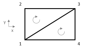
Schematic of part surface facet topology
|
|
Case02a
The present case considers sedimentation with propagation of two faults via fault seeding. Fault seeding requires the following data:
•Fracture_data with an assigned Coordinate_system (compulsory) • Fault_set linking the Fracture_data with the Part_geometry_set which defines the fault pathway as well as defining the seeding properties for the fault. •Fault_insertion to request fault seeding (prescribe the fault) at the elements intersecting the part geometry. In a case with sedimentation as the present one we may specify one Fault_insertion data structure per each sedimentation stage.
Fracture_data
Data File
|
|
* Coordinate_system NUM=1
Name "Fract01_direction"
Direction_cosines IDM=3 JDM=3
0.4473 0.0000 0.8944
0.0000 1.0000 0.0000
-0.8944 0.0000 0.4473
* Fracture_data NUM=1
Name "Fract01"
Propagation_model_name "PreExist"
Flow_model_name "SimpleHydro"
Conductivity_model_name "PermMult"
Permeability_multiplier 100
Coordinate_system 1
* Fracture_data NUM=2
Name "Fract02"
Propagation_model_name "PreExist"
Flow_model_name "SimpleHydro"
Conductivity_model_name "PermMult"
Permeability_multiplier 10000
Coordinate_system 1
|
1Two Fracture_data data structures are defined which are named "Fract01" and "Fract02" respectively 2For prescribed faults through fault seeding Propagation_model_name must be set to "PreExist". 3The perm enhancement for the continuum fault model requires to define the Flow_model_name keyword and set it to "SimpleHydro" 4In the present case perm enhancement based multipliers to the material permeability for fault elements is considered for both faults. This is done by setting the keyword Conductivity_model_name to "PermMult" and defining the Permeability_multiplier keyword to set the multiplier values which in this case are set to 100 and 10000 respectively. 5Definition and assignment of a Coordinate_system is compulsory for cases with prescribed (seeded) faults. In the present case both faults are assigned the same coordinate system. |
Fault_set
Data File
|
|
* Fault_set NUM=1
Name "Fault01"
Fracture_assignment "Fract01"
Insertion_type "Seeded"
Geometry_set "Fault01_part"
Seeding_variables IDM=1
"P_strnv"
Seeding_values IDM=1
0.05
* Fault_set NUM=2
Name "Fault02"
Fracture_assignment "Fract02"
Insertion_type "Seeded"
Geometry_set "Fault02_part"
Seeding_variables IDM=1
"P_strnv"
Seeding_values IDM=1
0.02
|
1The Fault_set are named Fault01 and Fault02 respectively. 2The corresponding fracture data are assigned to each fault 3Geometry_set keyword is used to assign the corresponding part geometry sets to each fault. Those part geometries will be used to seed the faults at the domain elements intersecting the geometry part. 4Seeding_variables and Seeding_values keywords are defined for both faults in order to consider strength decrease in fault elements. This will introduce a reduction in pre-consolidation pressure according to the value of imposed plastic volumetric strain (P_strnv) following the hardening data of the material. In this case different plastic volumetric strain values for each fault are defined being 0.05 and 0.02 for Fault01 and Fault02 respectively. 5If Seeding_variables and Seeding_values are not defined in Fault_set then only perm enhancement would be considered for the seeded faults. |
Fault_insertion
The present case considers fault seeding of both faults to the initial geometry at the second stage. Then, during subsequent stages there is sedimentation with fault seeding to propagate faults into the newly deposited units. Note that in this case it is demonstrated how to consider different propagation times for the different faults.
Data File
|
|
* Control_data
Control_title "Initialization"
* Fault_insertion NUM=1
Insertion_type "Seeded"
Units IDM=4
"Formation01"
"Formation02"
"Formation03"
"Formation04"
Faults IDM=2
"Fault01"
"Fault02"
Seeding_variables IDM=1
"P_strnv"
Seeding_values IDM=1
0.01
* Control_data
Control_title "Insertion"
* Fault_insertion NUM=1
Insertion_type "Seeded"
Units IDM=1
"Formation05"
Faults IDM=1
"Fault01"
Seeding_variables IDM=1
"P_strnv"
Seeding_values IDM=1
0.01
* Control_data
Control_title "Formation05"
* Fault_insertion NUM=1
Insertion_type "Seeded"
Units IDM=2
"Formation05"
"Formation06
Faults IDM=1
"Fault02"
Seeding_variables IDM=1
"P_strnv"
Seeding_values IDM=1
0.01
* Control_data
Control_title "Formation06"
* Fault_insertion NUM=1
Insertion_type "Seeded"
Units IDM=2
"Formation06"
"Formation07
Faults IDM=2
"Fault01"
"Fault02"
Seeding_variables IDM=1
"P_strnv"
Seeding_values IDM=1
0.01
* Control_data
Control_title "Formation07"
|
1A Fault_insertion data structure is defined in each stage in order to seed (prescribe) each fault listed in Faults keyword. Note that the following propagation assumtions are considered: i.Stage2: Both faults seeded to all formations from the initial geometry ii.Stage3: Fault01 propagates into the newly deposited unit "Formation05" iii.Stage4: Fault02 propagates into the newly deposited unit and the previous one "Formation05" and "Formation06" iv.Stage5: Both faults propagate up to the top surface into the newly deposited unit "Formation07". Note that Fault01 required to propagate through "Formation06" as well. 2The formations to which the listed faults are going to be seeded are specified. Note that in stage 5 both Formation06 and Formation07 need to be specified as Fault01 was not previously propagated through Formation06 3Definition of Seeding_variables and Seeding_values is compulsory in Fault_insertion data structure. Note however that the values specified in each Fault_set are the ones that will be used to calculate the strength (pc) decrease for each fault. 4Note that in HEX element meshes Element_size cannot be defined. |
|
Case02b
The present case is very similar to Case02a but in the present one a keyword to control fault width (a factor of number of elements) is introduced. Additionally different models for perm enhancement are used for the different faults for the sake of demonstrative purposes. Note that only the data different than Case01a is going to be discussed.
Fracture_data
Data File
|
|
* Fracture_data NUM=1
Name "Fract01"
Propagation_model_name "PreExist"
Flow_model_name "SimpleHydro"
Conductivity_model_name "PermMult"
Permeability_multiplier 100
Coordinate_system 1
* Fracture_data NUM=2
Name "Fract02"
Propagation_model_name "PreExist"
Flow_model_name "SimpleHydro"
Conductivity_model_name "PermCons"
Permeability 1E-10
Coordinate_system 1
|
1This case demonstrates that different models for perm enhancement for each fault may be adopted. Fract01 uses a perm multiplier model whereas Fract02 uses a constant perm value. |
Fault_set
Data File
|
|
* Fault_set NUM=1
Name "Fault01"
Fracture_assignment "Fract01"
Insertion_type "Seeded"
Geometry_set "Fault01_part"
Factor_for_seeding_width 0.8
Seeding_variables IDM=1
"P_strnv"
Seeding_values IDM=1
0.05
* Fault_set NUM=2
Name "Fault02"
Fracture_assignment "Fract02"
Insertion_type "Seeded"
Geometry_set "Fault02_part"
Factor_for_seeding_width 1.5
Seeding_variables IDM=1
"P_strnv"
Seeding_values IDM=1
0.02
|
1The keyword Factor_for_seeding_width is used to define the fault width. This is achieved by defining a factor of the average fault element length in order to determine the width over which elements will be identified as fault elements after seeding. |
|
A selection of result files for the project are provided in directory: ParaGeo Examples\General Examples\Ex_010\Case02\Results.
The figure below shows the sequence of fault propagation for both Case02a and Case02b.
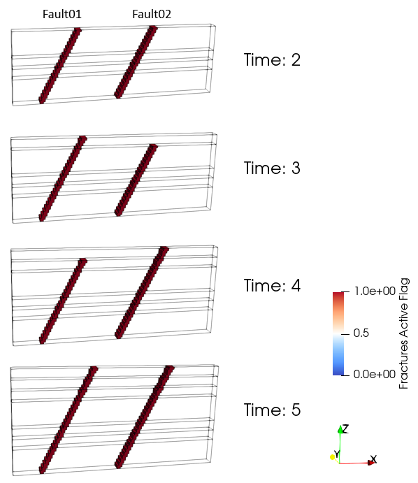
Sequence of fault propagation through the simulation
The figures below show the pre-consolidation pressures and fracture permeabilities for both faults in Case02a. Note that because in the present case the porosities decrease with depth the pre-consolidation pressure increases and permeability decreases with depth. Note the different values for both faults as different data is defined for each one. Note as well as the second layer (Formation02) shows a different trend in values for both perm and pre-consolidation pressure as is the only group assigned Sand material (and consequently the properties are expected to be different than groups assigned Shale material).
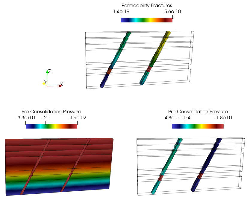
Permeabilities and pre-consolidation pressures for both faults in Case02a. Note that Formation02 is the only group assigned Sand material and consequently shows different trends than the remaining groups
The figure below shows the enhanced perm in both faults for Case02b. Note that whereas Fault01 shows a decreasing perm with depth (because a perm multiplier has been used) Fault02 shows a constant value set to 1E-10 as defined in the data. Note as well the different fault widths in both faults as defined by the keyword Factor_for_seeding_width (set to 0.8 for Fault01 and 1.5 for Fault02).
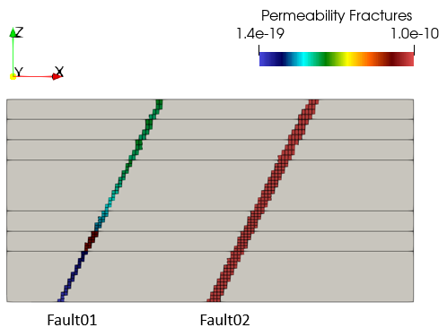
Permeability for both faults in Case02b.
|


