Case01 Import, Processing and Export to a new FracMan file
The present example demonstrates:
1.Import of the FracMan file containing definition of a DFN
2.Processing of the fracture distribution
3.Output of the processed fracture distribution to a new FracMan file
The data file for the example is in: Fract_001\Case01\Data\fract_001_Case01.dat. The data is identical to the one in Case00 except for the data defined in Fracture_set which is described below.
Fracture_set
In the present case Fracture_set is defined with data to:
1.Process the fractures defined in the imported FracMan file by applying offset and scaling transformations.
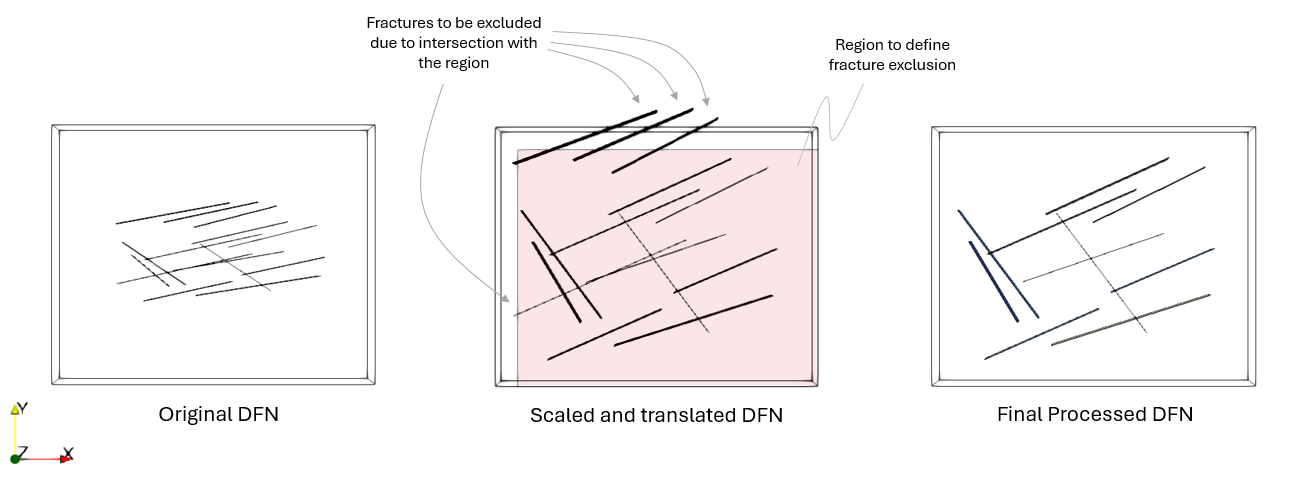
2.Define a region so that only the transformed fractures fully contained within that region will be considered (fractures outside or intersecting the region will be discarded). This ensures fractures to be automatically discarded that will lead to errors or meshing issues (fractures from a set need to be fully contained within a single volume and not intersect any boundary).
3.Output the processed / transformed DFN into a new FracMan file.
Data File |
|
* Fracture_set NUM=1 ! ------------------------------------ Name "Set_1" Volume 1 Active_flag 1 Pre_intersect_out_flag 1 Offset IDM=3 /Offset in X/ -40.0 /Offset in Y/ -50.0 /Offset in Z/ 0.0 Scale IDM=3 /Factor in X/ 1.25 /Factor in Y/ 2.5 /Factor in Z/ 2.0 Region_type "Rectangle" Region_size IDM=6 /X Y Z min/ 733 0 0 /X Y Z max/ 1000 210 50 Fab_file_output "frac_sample_2"
|
1.A name for the fracture set is defined (arbitrary). 2.The Volume in the ParaGeo geometry that will be associated with the imported DFN is specified. 3.Active_flag set to 1 indicates that the fracture set must be processed. Definition of this data is not required for the present case as the default is 1. 4.Pre_intersect_out_flag is defined with a value of 1 to terminate the simulation before performing any geometry intersection. This is compulsory in the present case as the geometry is not being meshed. 5.Offset and Scale keywords are defined to specify the corresponding input values to apply the transformations. 6.The rectangular region (Region_type "Rectangle") for excluding fractures outside or intersecting the region is defined by providing the coordinates of two opposite corners. In the present case the region is defined slightly smaller than the model domain. 7.Fab_file_output is used to define the name of the FracMan file being output which will contain the processed / transformed DFN.
|
Results
The results for the project are located in Fract_001\Case01\Results. This includes:
1.The geometry plot file (fract_001_Case01_001.gmr) that may be visualized in ParaView by loading the fract_001_Case01_gmr_001.xmf file.
2.The output FracMan file frac_sample_2.fab containing the processed DFN definition.
3.The frac_sample_2.fraclist ASCII file containing the list of original fracture number, the corresponding new fracture number and the fracture set being assigned.
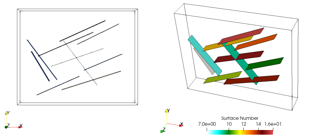
In the figure below we can see the processed DFN. Note that there is a smaller number of fractures compared to Case00 with the original DFN.
View of the processed DFN output to the new FracMan file
The plots below show the comparison of the processed DFN with the original DFN, noting that the fractures which intersect the region after being transformed have been excluded.
View of the processed DFN output to the new FracMan file compared to the original DFN
|


