Case00 Import of the FracMan DFN for visualisation only
The present example demonstrates the import of a DFN defined in a FracMan file for visualisation purposes only.
The data file for the example is in: Fract_001\Case00\Data\fract_001_Case00.dat. The data file includes the minimal (compulsory) data required to import and visualize the DFN defined in the FracMan file:
i.Definition of the ParaGeo model geometry for which the fracture distribution will be imported (nodal_data, Geometry_line, Geometry_surface and Geometry_volume). This will provide a reference to the location of the fractures within the geometry.
ii.Group_control_data and Group_data data structures
iii.Material_data and Fluid_properties
iv.Include data to read the FracMan file
v.Fracture_set with the minimal data required to visualize the DFN defined in the FracMan file
vi.Control data (Control_data) to run a single step. Note that in this case the data contains keywords for coupled simulations but this is not compulsory.
The following describes data relevant to the fracture import.
Include
Include data structure is used to import the FracMan data.
Data File |
|
* Include ! --------------------------------- Filename "frac_sample.fab"
|
1The name of the FracMan file is defined. This file is located in the same folder as the main data file. |
Fracture_set
In the present case Fracture_set is defined with minimal data as the aim is to visualize the original DFN defined in the FracMan data file.
Data File |
|
* Fracture_set NUM=1 ! ------------------------------------ Name "Set_1" Volume 1 Pre_intersect_out_flag 1
|
1A name for the fracture set is define (arbitrary). 2The Volume in the ParaGeo geometry that will be associated with the imported DFN is specified. 3Pre_intersect_out_flag is defined with a value of 1 to terminate the simulation before performing any geometry intersection. This is compulsory in the present case as the geometry is not being meshed. |
Results
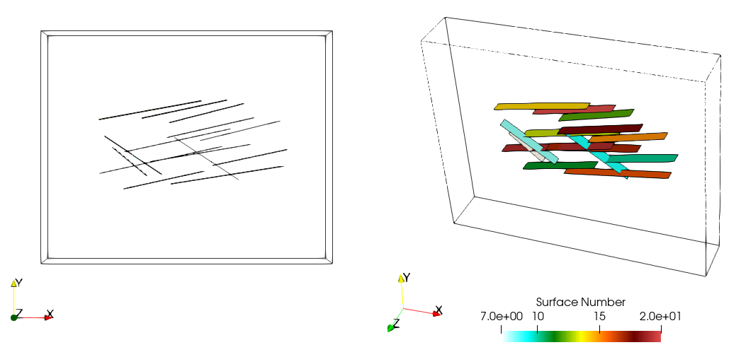
The results for the project are located in Fract_001\Case00\Results. This is a single geometry plot file (fract_001_Case00_001.gmr) that may be visualized in ParaView by loading the fract_001_Case00_gmr_001.xmf file.
In the figure we can see the imported fractures. These are numbered from 7 to 20 as the first 6 ID numbers are taken by the surfaces used to define the ParaGeo geometry.
View of the DFN defined in the FracMan file
|

