Step04 Restoration
The data files for restoration simulation using both; couple freedoms constrain on boundary nodes (on a column of nodes basis) and membrane elements on top surface for bed length preservation are in: Geol_002b\Case01\04_Restoration\Data. Those files are:
1.Geol_002b_Case01_rest.dat main datafile for the restoration simulation. The data relevant to both, application of the couple freedoms constrain on the boundary and usage of the membrane elements to preserve bed length is discussed in detail below.
2.Geol_002b_Case01_geom.geometry datafile with the group data read via the data structure Include. This is carried from the previous workflow step were the groups were renumbered. Further edits are made to assign the same materials for each layer and same hourglass properties as in Geol_002 case. Hence those edits are not discussed in detail here.
3.Geol_002b_Case01_geomB.dat datafile generated during the previous workflow step containing the Geometry_set data required to apply the couple freedoms constrain. This is read via the keyword Include defined in the main data file.
4.Geol_002b_Case01_geomB.geo geometry for the model.
5.Geol_002b_Case01_rest_geostatic.dat containing the geostatic data and compaction curves defining the initial porosities and the decompaction curves to be used during restoration. This is identical to the geostatic data for Geol_002 example.
6.Geol_002b_Case01_RestSurf01.dat datafile containing the restoration surface which is identical to the one in Geol_002 example.
7.Geol_002b_rest01_Ss_Si_Sh_Ca.mat material datafile containing the materials used in the simulation. Note that in contrast with Geol_002 example in the present example we do not consider directional decompaction during the first restoration stage. Therefore there is no need to update the materials as vertical decompaction is used during the entire simulation.
Following is a description of the data relevant to both usage of coupled freedoms and membrane elements defined in Geol_002b_Case01_rest.dat datafile.
Coupled Freedoms
|
Membrane elements
In the second and third stages Restoration_data is re-specified with data relevant to usage of membrane elements for approaching bed length preservation. The difference between the data for the second and third stages in this case is the Operation_type, set to "Translate" for the second stage and set to "Restore" for subsequent stages.
|
Results
The results for the present workflow steps are provided in Geol_002b\Case01\04_Restoration\Results. Note that only a selection of the results is provided.
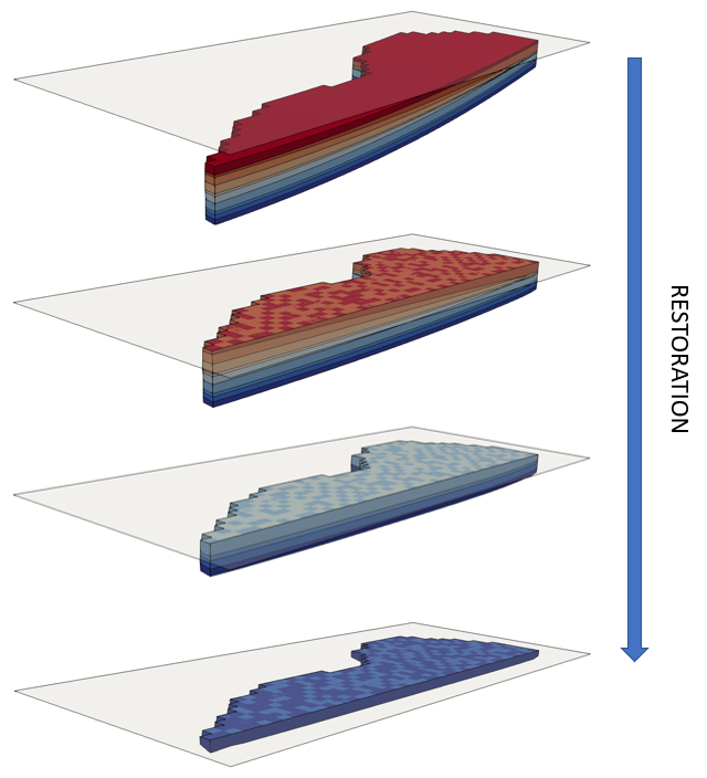
The restoration was completed in 10 minutes using a single processor (3.6 GHz clock speed). A sequence of few restoration steps can be seen in the figure below.
Sequence showing initial geometry and geometry at the end of 3 restoration stages
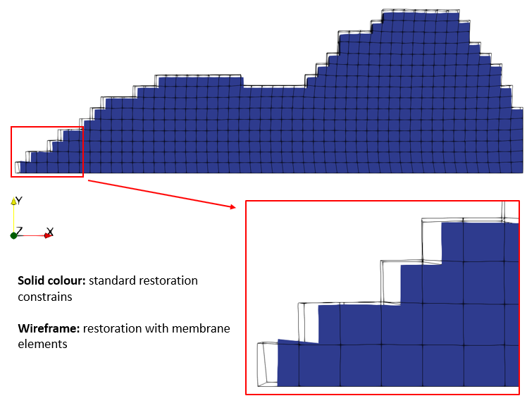
In the figure below the final restored geometry for the present case is compared to the final restored geometry assuming standard restoration constrains (no bed length preservation via the membrane elements). As can be observed the present case has a larger final restored geometry than the case with standard constrains. For the considered geometry the difference is rather small because of the low relief in the restored geological structure, however the difference may become more significant with structures showing more relief (e.g. see the flexural fold example shown below).
Comparison between the final restored geometry for the present case including membrane elements (wireframe) and final geometry for a case with standard restoration constrains (solid blue colour)
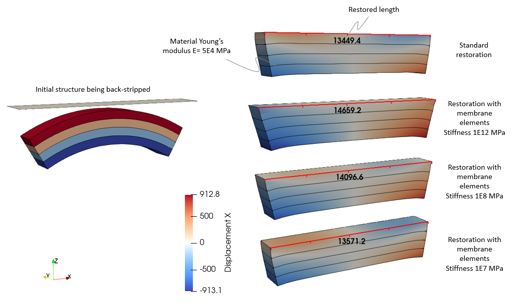
Example showing the effect of different membrane element stiffness in the restored bed-length during back-stripping of a flexural fold. Note how the case with high stiffness (1E12) shows positive displacements in the X direction to the right of the axial plane of the fold (pinned plane) and negative displacements to the left. The rest of the cases show displacements in the opposite direction for nodes close to the top surface, indicating bed-length contraction.
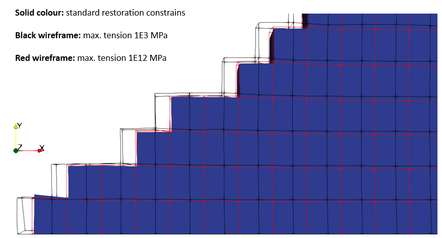
IN the figure below the effect of the maximum tensional stress is demonstrated. Increasing such value from 1·103 MPa to 1·1012 MPa reduces significantly the extra length recovered due to the usage of the membrane elements as it results in a final restored length very similar to the restoration with standard assumptions.
Comparison of two cases using membrane elements with different maximum tension stress with case with standard restoration constrains.
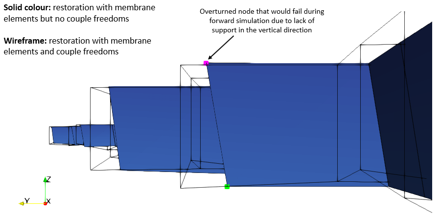
In the picture below the final restored geometry for the present case is compared to a case that also used the membrane elements but did not include the couple freedoms constrain for the boundary. As can be seen the later case has overturned nodes in some boundary elements where the nodes in the top surface are located "more outwards" than the corresponding nodes at the base. In some cases where such overturn is rather pronounced, this becomes a sub-optimal initial geometry for the forward simulation during which instabilities may occur as the overturned node may fall downward due to the lack of support in the vertical direction.
View of comparison of boundary elements for the final restored geometries for the present case which includes membrane elements and couple freedoms (wireframe) and a case with membrane elements but not couple freedoms constrain (solid colours)
|

