SPSK_2 model (poroelastic behaviour)
In this case the Shale lithology is identical to previous case whereas Reservoir lithology considers poroelasticity only (no SR4 plasticity). Material properties are described in SPSK_1 model page so only the differences are discussed here.
Material_data
Data File |
|
* Material_data NUM=2 ! --------------------------------- Material_name "Reservoir" Units IDM=4 /Stress/ "Pa" /Length/ "m" /Time/ "years" /Temperature/ "Celsius" Grain_stiffness 30000E6 ! Pa Grain_density 2710.0 ! Kg/m3 Porosity 0.15 Elastic_model_type 1 ! Isotropic Elasticity Elastic_properties IDM=2 /Young's Modulus (E)/ 1000.0E6 ! Pa /Poisson's Ratio (V)/ 0.25 Porous_elasticity_type 1 ! Cam Clay Porous_elastic_properties IDM=2 /"Bulk Modulus at Deposition (K0)"/ 10.0E+6 ! Pa /"Unloading Modulus (Kappa)"/ 0.02 Permeability_type 2 Permeability_vs_porosity IDM=20 JDM=2 /Porosity/ 0.01 0.02 ... 0.5 /Permeab./ 0.0006853 0.0054824 ... 85.6625 Biot_type 1 Biot_constant 1.0 Fluid_saturation 1.0 Singlephase_fluid 1
|
1.All material properties are identical except that Reservoir properties do not include plasticity. Thus difference with case SPSK_1 model is that in this case Reservoir material does not contain any data concerning: a.Plasticity model and its relevant properties b.Hardening model and its relevant properties c.Regularisation model and its relevant properties
|
Results
The result files for the project are in directory: IX_002\SPSK_2\Results
A case considering poroelastic behaviour for the reservoir lithology has been simulated. The main effects of plasticity on stresses, porosity and displacements have been discussed in IX_001 Case2. In the present case it is interesting to note the effect of plasticity on pore pressure evolution and on stress distribution.
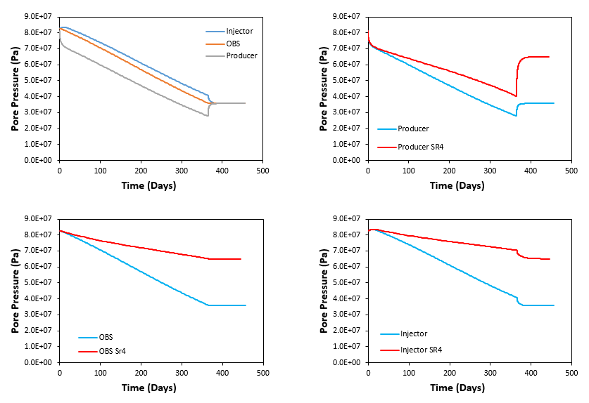
In the figure below the evolution of pore pressure in the three output points (injector, observation and producer) is shown. Also it is provided a comparison on pore pressure results for each of the points between the poroelastoplastic and poroelastic case that help to discuss the differences. It can be seen that:
1.As in the previous case pore pressure in the injector is higher than in producer location in order to generate a pressure gradient and stimulate production in the producer well. In this case pore pressure for the observation point is also in between the pore pressure at injector and pore pressure at producer locations.
2.As in the previous case pore pressure after shut down is equilibrated within the reservoir.
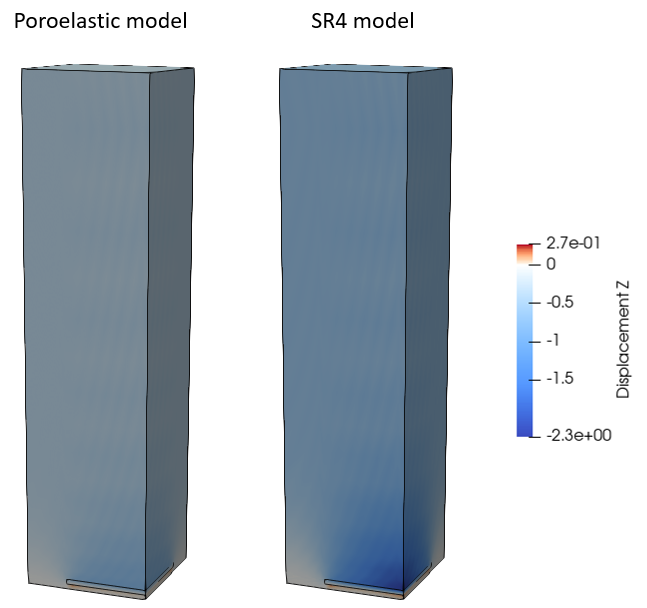
3.Interestingly pore pressure in the three point locations is lower for the poroelastic case than for the SR4 case. This is can be explained by the fact that in the poroelastoplastic case (SR4) the plasticity captures compaction due to pore collapse as pressure drops reducing further the pore volume. Then two effects resulting from such compaction contribute to the higher pore pressure in the poroelastoplastic case: a.There is larger subsidence (vertical displacement) in the poroelastoplastic (SR4) case and hence more weight of the overburden being supported by the pore fluid than in the poroelastic case (see below the vertical displacement contours for the two cases). b.The lower porosity in the poroelastoplastic case results in lower permeability, what hinders pressure reduction during production.
Evolution of pore pressure at the injector, observation and producer point locations (top left) and comparison of pore pressure evolution for the poroelastic and the poro-elasto-plastic (SR4) cases.
Comparison of vertical displacement contours for the poroelastic and the poroelastoplastic (SR4) cases
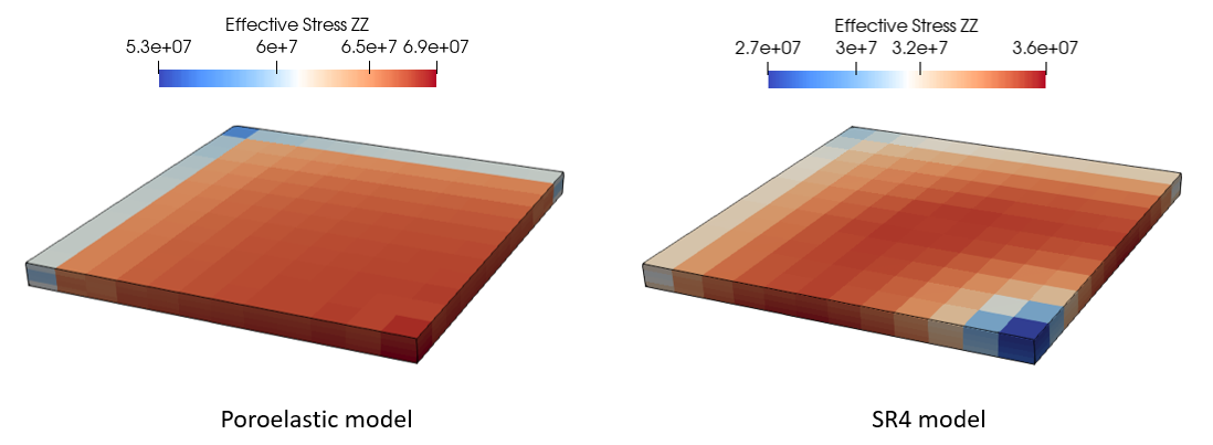
Pore pressure and displacements are different in the poroelastic and poroelastoplastic cases and hence distribution of stresses is also expected to show differences. In the figure below vertical effective stress contours in the reservoir are shown from which it can be seen that:
1.The poroelastoplastic case shows lower effective stresses. This is due to the higher magnitude of pore pressure.
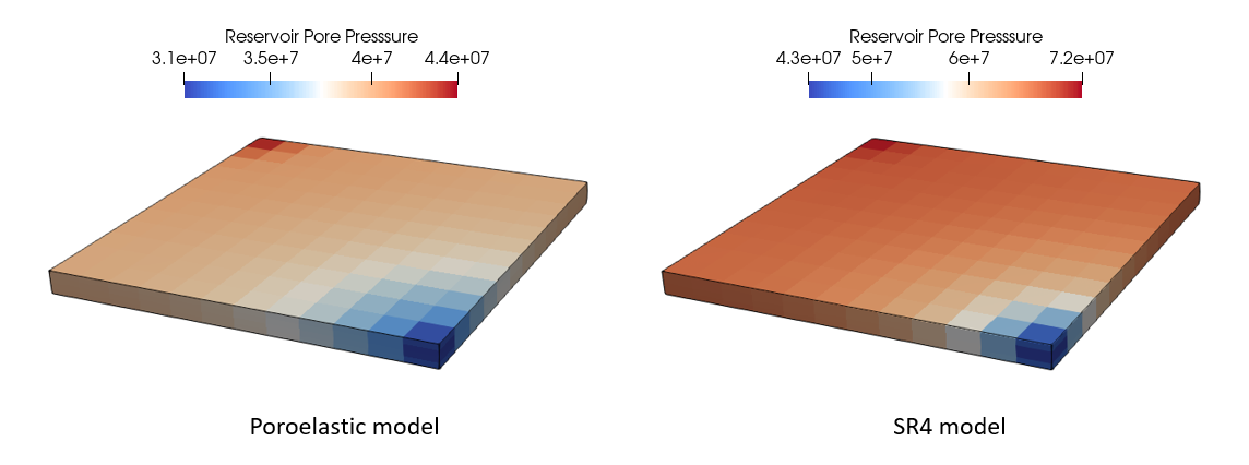
2.The poroelastoplastic case has the lowest stress magnitude at the producer well location whereas the poroelastic case has the lowest effective stress magnitude at the injector well location. This is because before shut down of production in the poroelastoplastic case there was a higher variation in the pore pressure magnitudes across the reservoir (a difference of 2.9·107 Pa in the poroelastoplastic case whereas in the poroelastic case there was a difference of 1.3·107 Pa). Thus after shut down and pore pressure equilibration in the reservoir there was a larger pore pressure increase at the producer well location for the poroelastoplastic case leading to more vertical effective stress reduction due to elastic unloading (see the comparison in pore pressure increase for the two cases in the figure above).
Comparison of vertical effective stress contours in the reservoir for the poroelastic and poroelastoplastic (SR4) cases at the end of the simulation
Comparison of pore pressure contours in the reservoir for the poroelastic and poroelastoplastic (SR4) cases before the shut down |


