Diagenesis Model Behaviour
In this manual page the more complex aspects of the effect of the diagenetic overprint on sediments in defining the evolutionary behaviour will be addressed. This will particularly focus on:
1.The evolution of stresses during diagenesis depending on the defined diagenesis flow rule (Compaction_direction_factor)
2.The effect of the diagenetic-induced increased strength (increase in pc)
3.The effect of diagenesis on pore pressure
To that end different single-element model setups will be used to perform sensitivity analyses. The datafiles used to perform the sensitivity analysis are provided but because the objective is to facilitate a better understanding on the model behaviour, the data structures and data inputs of such models will not be discussed in detail here although a brief description of the models is provided. All the model data files and material files are in Mat_002/Model_behaviour/Data whereas the spreadsheets with the results are in Mat_002/Model_behaviour/Results.
Modelling diagenetic compaction in ParaGeo
Before discussing the modelling results is important to understand how the diagenetic porosity loss is being applied in Parageo. Because strain is an outcome from the model (the code solves for displacements) is more convenient to perturb the stress field. Thus, the code reduces the internal stress in the material to trigger the calculated diagenetic compaction provided by the diagenesis model. This simulates "weakening" of the internal material framework which triggers further compaction. This is explained in the two figures below (it should be noted that the numbers are selected arbitrarily):
The first figure exemplifies a diagenetic step for the case for uniaxial compaction flow rule defined in Diagenesis_data (Compaction_direction_factor = 0.0). A reduction in the internal effective stresses corresponding to uniaxial strain is imposed (framework weakening). This triggers diagenetic compaction until the vertical stress is balanced back to the external load. Because the stress reduction was imposed assuming uniaxial strain, horizontal effective stress recovers its original value.
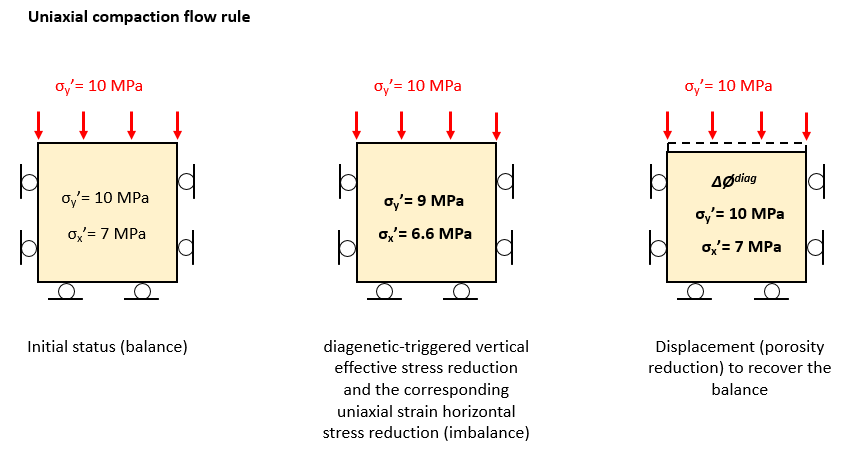
Schematic example demonstrating the internal code procedure for diagenesis compaction. In this example a uniaxial compaction flow rule and no diagenetic hardening is assumed.
The second figure exemplifies a diagenetic step for the case for hydrostatic compaction flow rule defined in Diagenesis_data (Compaction_direction_factor = 1.0). Because diagenetic compaction is set as hydrostatic a reduction in the internal vertical and horizontal effective stress with the same magnitude is imposed (framework weakening). This triggers diagenetic compaction until the vertical stress is balanced back to the external load. The horizontal effective stress increases according to Poisson's ratio by Δσx' = Δσy' · ν · (1-ν)-1 where ν is the Poisson's ratio and Δσy' is the resulting increase in vertical effective stress required to achieve balance with the external load. Note that the final horizontal effective stress value is lower than the initial one.
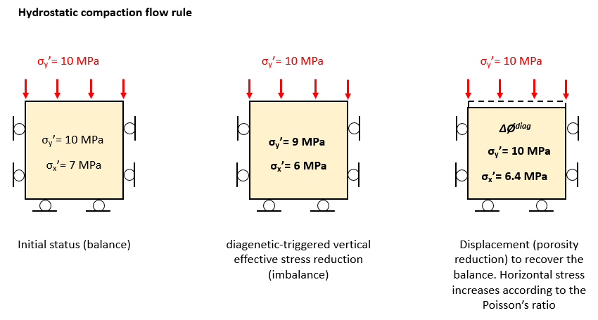
Schematic example demonstrating the internal code procedure for diagenesis compaction. In this example a hydrostatic compaction flow rule and no diagenetic hardening is assumed.
Models description
The initial conditions for the single element models are representative of sediment in hydrostatic conditions at 2000 m burial depth. To determine such conditions, first an arbitrary shale material was defined (named "Shale" in the Shale_diag.mat file provided). Note that in such material the Aun parameter in the poroelasticity law is set to 0.0 in order to consider dependence of the bulk modulus solely on pc (and hence in porosity) and not in the effective mean stress because:
1.This is more appropriate for evolutionary models at geological time scales where bulk modulus and young modulus are not expected to decrease much due to unloading (e.g. after an eroding event)
2.This simplifies understanding of the stress paths in the present exercise
Then an hydrostatic consolidation column model using the defined Shale material was simulated ("Consolidation.dat"). The results at 2000 m depth were then extracted to define:
1.The initial conditions for the single element models
2.A new material (named "Shale_200m" in the provided "Shale_diag.mat" file) with the reference porosity (Ø0) and reference pc (pc0) representative of the material at 2000 m burial depth
Such conditions/parameters were:
Ø0 |
0.3764 |
- |
pc0 |
-16.6 |
MPa |
σy' |
-18.74 |
MPa |
σx' |
-14.1 |
MPa |
Pore Pres. |
19.63 |
MPa |
σy |
38.37 |
MPa |
Then for the present exercise a Diagenesis_data with the following model parameters is defined and assigned to the "Shale_2000m" material:
ΔØdiagmax |
0.15 |
Reaction model |
Exponential |
Tin [0C] |
70 |
A [1·Ma-1] |
0.12 |
m |
1 |
n |
1 |
Cementation model |
Enhanced_pt |
Δptmax [MPa] |
2 |
Compaction model |
Enhanced_pc |
Fpc |
(case dependent) |
Comp. dir. fact. |
(case dependent) |
It should be noted that usage of "Enhanced_pc" compaction model (which does not consider change in hardening parameters λ and κ) was chosen for the sake of simplifying interpretation and discussion of the results.
Once the material to be tested was established the single element model is defined with initial conditions representative of 2 km of burial depth and boundary conditions simulating 1 km of extra burial over a time period of 10 Ma followed by a hiatus period of few 10s of Ma. It should be noted that the initial temperature is set below the threshold temperature for the diagenetic reaction during initialization and starts at 70 ºC during the burial simulation (which corresponds to a surface temperature of 10 ºC and a thermal gradient of 30 ºC/Km). Three different single element models with slightly different setups are defined:
•Drained thermal burial model: A model under drained conditions in which only the temperature increase corresponding to extra burial of 1 km is applied (the increase in stress and pore pressure is neglected). This allows to isolate and understand the effects of diagenesis.
•Drained burial model: In this model the boundary conditions for stress, pore pressure and temperature for extra burial of 1 km in hydrostatic conditions are applied.
•Undrained thermal burial model: With only the temperature boundary conditions being applied, this model focuses on understanding the effects of diagenesis in generating overpressure.
A History_point is used to output the results which are provided in the Mat_002_model_behaviour_history.xlsx spreadsheet.
Results
Drained thermal burial model
Comparison of results with diagenetic reactions considering different compaction direction factors are shown below for cases with and without chemical hardening. From the results it can be seen that:
1.Vertical effective stress is constant for all cases provided that only thermal boundary conditions corresponding to 1 km of burial is applied (this facilitates to isolate the diagenetic effects on stress evolution)
2.For cases with compaction direction factor = 0 there is no reduction in horizontal effective stress because the diagenetic compaction is uniaxial
3.For cases with compaction direction factor > 0 as diagenetic porosity loss increases horizontal effective stress decreases, leading to decrease in effective stress ratios and increase in q/p' ratios .
4.The larger the compaction direction factor the larger the horizontal effective stress reduction (as expected). This leads to lower effective stress ratios and larger q/p' ratios.
5.For a given compaction direction factor, the cases with chemical hardening (increase in pc) lead to larger reduction in horizontal effective stresses compared to the case with no chemical hardening. This is because due to the poroelastic law the bulk modulus (K) increases with pc. Therefore the case with chemical hardening will require a larger stress reduction to achieve a given diagenetic porosity loss compared to the case with no hardening.
6.The stress path evolves towards lower p' and higher q values due to the constant σy' and reduction in both σx' and σz'. As expected the larger reduction in p' and increase in q is observed for the case with chemical hardening due to the larger horizontal stress reduction for such case.
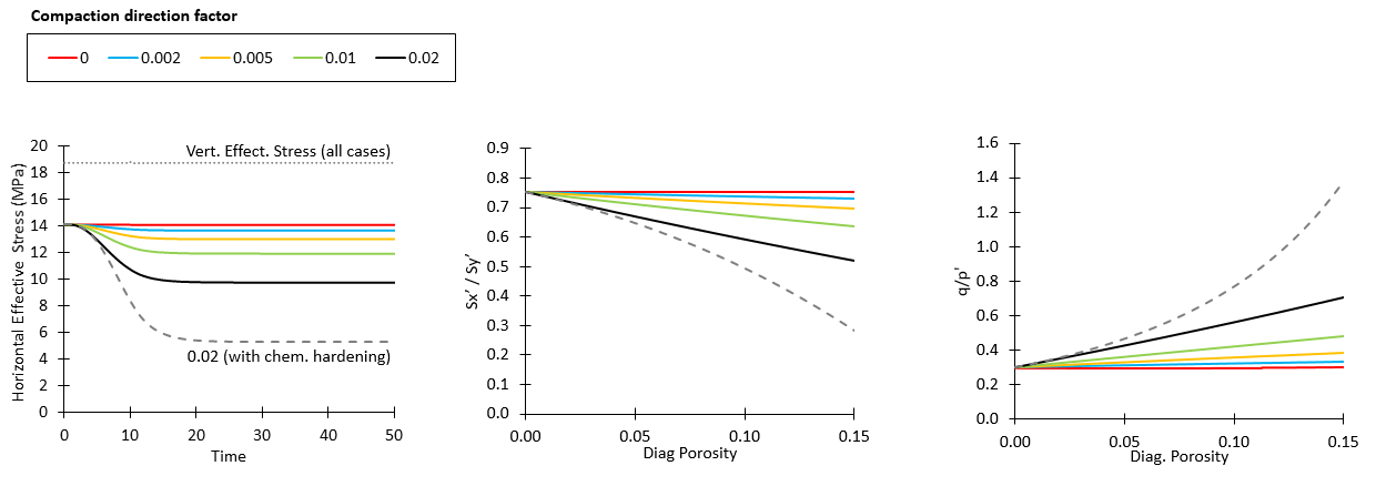
Effect of the compaction direction factor (flow rule) in stresses for the case with no diagenetic hardening (Fpc= 0.0). The curves for case with compaction direction factor 0.02 and Fpc= 1.0 are displayed with discontinuous lines for reference.
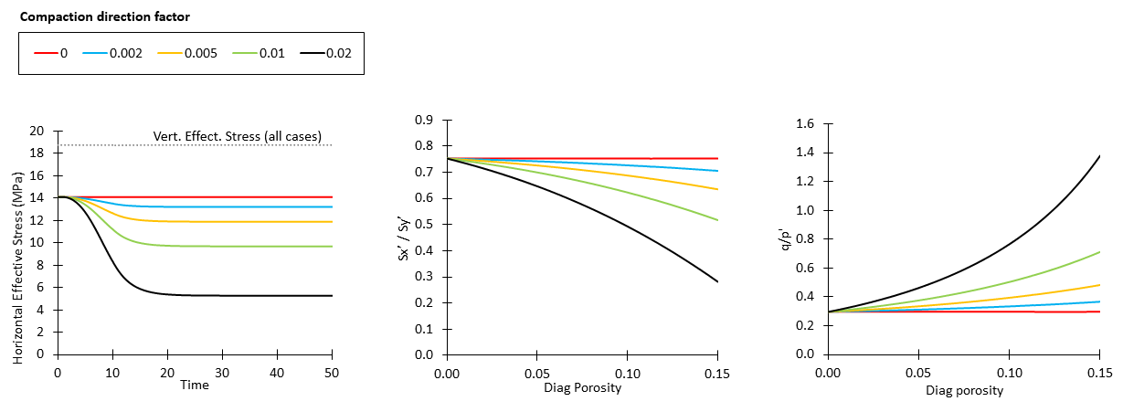
Effect of the compaction direction factor (flow rule) in stresses for the case with maximum diagenetic hardening (Fpc= 1.0)
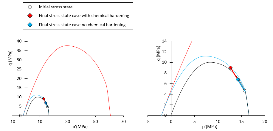
Comparison of stress paths and final yield surfaces for case with compaction direction factor 0.02 with and without chemical hardening. Blue colours are used for case without chemical hardening and red clour is used for case with chemical hardening. Initial yield surface is shown in black.
Drained burial model
Comparison of results with diagenetic reactions considering different compaction direction factors are shown below for cases with and without chemical hardening. It should be noted that although the burial phase happened from t=1 Ma to t=11 Ma the diagenesis reaction continues beyond that time until c.a. t=30 Ma. From the results it can be seen that:
1.Vertical effective stress increases during the burial phase for all cases.
2.For the considered compaction direction factors cases with no chemical hardening the horizontal effective stress also increases during burial phase. However there is a slight decrease in effective stress ratio and an increase in q/p' ratio even for the case with compaction direction factor 0.0 (uniaxial diagenesis). This is probably an effect of the competing stress changes due to burial (mainly plasticity) and diagenesis (elasticity). Note that in the absence of diagenesis the effective stress ration and q/p' ratio remains constant.
3.After the end of the burial phase (t=11 Ma) there is further reduction in horizontal effective stress due to the ongoing diagenesis at constant temperature.
4.The cases that considered chemical hardening show the same trends but with larger reductions in horizontal stresses. This in turn results in lower effective stress ratios and higher q/p' ratios. As discussed previously for the drained thermal model this is an effect of the poroelastic law, that increase the bulk modulus (K) when pc increases, thus requiring a larger stress change to achieve a given porosity change. In this model in addition there is the effect of overconsolidation on the development of horizontal effective stress during burial, which is governed by elasticity rather than plasticity.
5.The stress paths for the cases with compaction direction factor 0.02 with and without chemical hardening are very different form each other: while the case with no chemical hardening draws a stress path slightly more inclined than a k0 path during the burial phase followed by a reduction in p' with an increment in q during the diagenesis without burial phase, the case with chemical hardening shows a pseudo-vertical path during the burial phase with large increase in q followed by a reduction in p' with an increment in q during the diagenesis without burial phase. This comparison shows that the chosen diagenesis parameters will have a strong influence on the stress path.

Effect of the compaction direction factor (flow rule) in stresses for the case with no diagenetic hardening (Fpc= 0.0)

Effect of the compaction direction factor (flow rule) in stresses for the case with maximum diagenetic hardening (Fpc= 1.0)
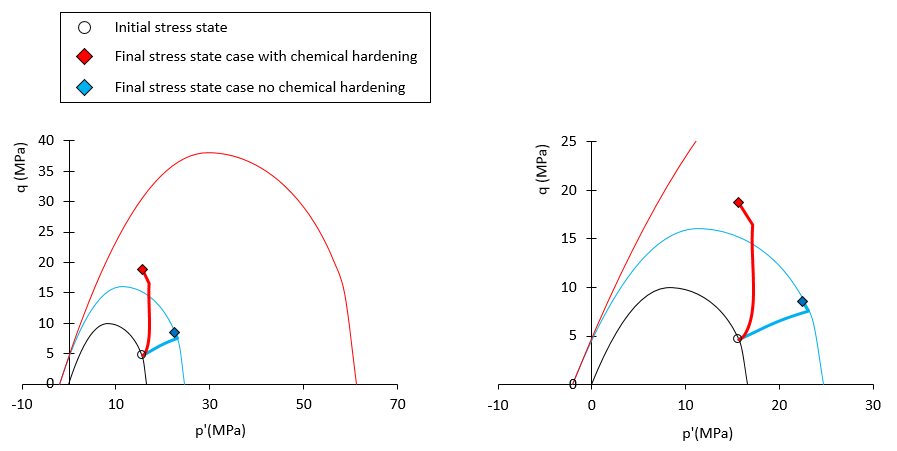
Comparison of stress paths and final yield surfaces for case with compaction direction factor 0.02 with and without chemical hardening. Blue colours are used for case without chemical hardening and red clour is used for case with chemical hardening. Initial yield surface is shown in black.
Undrained thermal burial model
For the present model the simulation has only been undertaken until time t=6 Ma because before that time a steady state solution for pore pressure, stresses and porosity has been achieved. It should be noted that such steady state is reached because the diagenesis model will stop to decrease stresses once the stresses reached 0 MPa value (it does not introduce tensional stresses). At this point the rock would have developed hydraulic fracture. The results show that:
1.The undrained conditions and the constant overburden load in this model allow to demonstrate the potential of diagenesis in generating large amounts of overpressure. It can be seen that pore pressure increased from the initial value of 19.6 MPa to a maximum value of 38.4 MPa in just 1.76 Ma.
2.In the 1.76 Ma the increase in pore pressure lead to a reduction of effective stresses to 0 MPa.
3.It should be noted that although the diagenetic porosity loss at time 1.76 Ma is ~ 0.008, porosity has only decreased by ~ 0.002 as the diagenesis porosity decrease is competing with elastic unloading.
4.It should be noted that diagenesis porosity loss is still ongoing after time 1.76 Ma when the stresses reach zero value (as well as the pc increase in the case with hardening). This is because the diagenesis porosity loss is calculated from the reaction model, so it will continue until the maximum diagenetic porosity loss is achieved. Porosity value on the other hand accounts for the true porosity lost by diagenesis achieved by the diagenetic-induced stress reduction, and because stress reduction stops when 0 value is reached, porosity value is constant after such time.
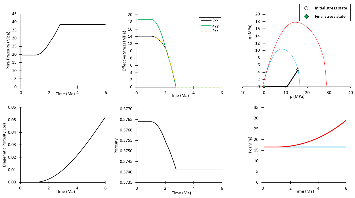
Results for uniaxial diagenetic compaction for both, case with maximum diagenetic hardening and case with no diagenetic hardening. Both cases provide identical results except the increase in pc and hence the final yield surface where the blue color is used for case with no hardening and red color is used for case with chemical hardening.
Diagenesis in a column model
After using single element models to understand the behaviour of the diagenesis model a uniaxial burial column model is also simulated in order to provide further insights on the usage of the diagenesis model in more typical scenarios. The model is initialized with 1.9 Km of sediment in hydrostatic conditions and 15 extra layers of 200 m thickness are deposited at 100 m/Ma rate. The model is coupled for mechanical and fluid flow fields whereas the temperature is prescribed according to a surface temperature of 10 ºC and a thermal gradient of 30 ºC/Km. Three cases are considered:
1.Case with no diagenesis (mechanical compaction only)
2.Case with diagenesis with no diagenetic hardening
3.Case with diagenesis with diagenetic hardening
The shale material is the same used previously with the compaction direction factor set to 0.02. The porosity-permeability curve is descrived according to a power law function of the form k=A·Øn with A = 1.26·10-17 and n=4.5 which is a function representative of 80% shale with 20% siltstone (see figure below).
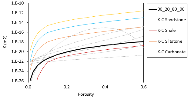
Considered porosity-perm curve. Kozeny-Carmen curves for typical Shale, Siltstone, Sandstone and Carbonates are displayed for reference. The discontinuous grey lines are curves for Yang and Aplin model from clay fraction 0.0 to 1.0 in increments of 0.2.
The results in the figure below show that:
1.The diagenesis leads to extra overpressure where the case with no chemical hardening generating more overpressure than the case with diagenetic hardening. This is because in the case with diagenetic hardening the overconsolidation prevents further mechanical compaction and hence further potential of generating overpressure.
2.The case with no diagenetic hardening reached lower porosities than the case with diagenetic hardening, again because the overconsolidation prevented further mechanical compaction once the diagenesis took place.
3.Porosities at depths shallower than ~ 2.2 km are larger for cases with diagenesis than the case without diagenesis. This is because the increased overpressure at depth due to diagenesis and the upward flow increased overpressure in the shallower sections leading to better porosity preservation. Note that the case without diagenetic hardening (case with largest overpressure) predicts higher porosities at depths above 2 km than the case with diagenetic hardening.
4.Vertical effective stresses show reduction with overpressure. At 3.5 km depth the case with no diagenesis and the case with diagenetic hardening show almost the same vertical effective stress although their pore pressure prediction differ by ~2MPa. This is because the total stress from the overburden weight in the diagenetic case is higher due to the lower porosities.
5.Horizontal effective stresses show reduction due to both, overpressure and diagenesis, with the case with diagenetic hardening showing a larger reduction.
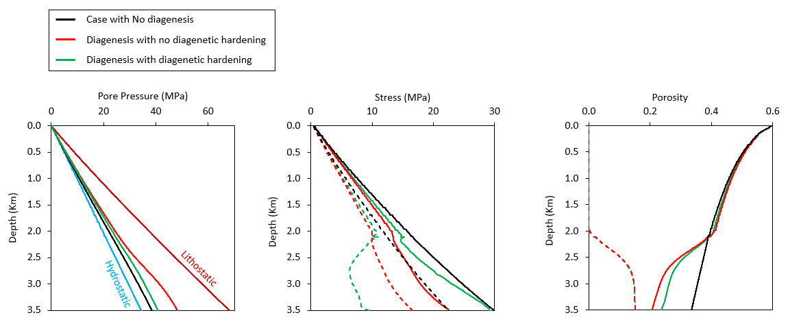
Results for the column model with sedimentation. In the center figure continuous and discontinuous lines are used to represent vertical and horizontal effective stresses respectively. In the right hand figure continuous lines are used to represent porosity whereas discontinuous lines are used to represent diagenetic porosity loss.
