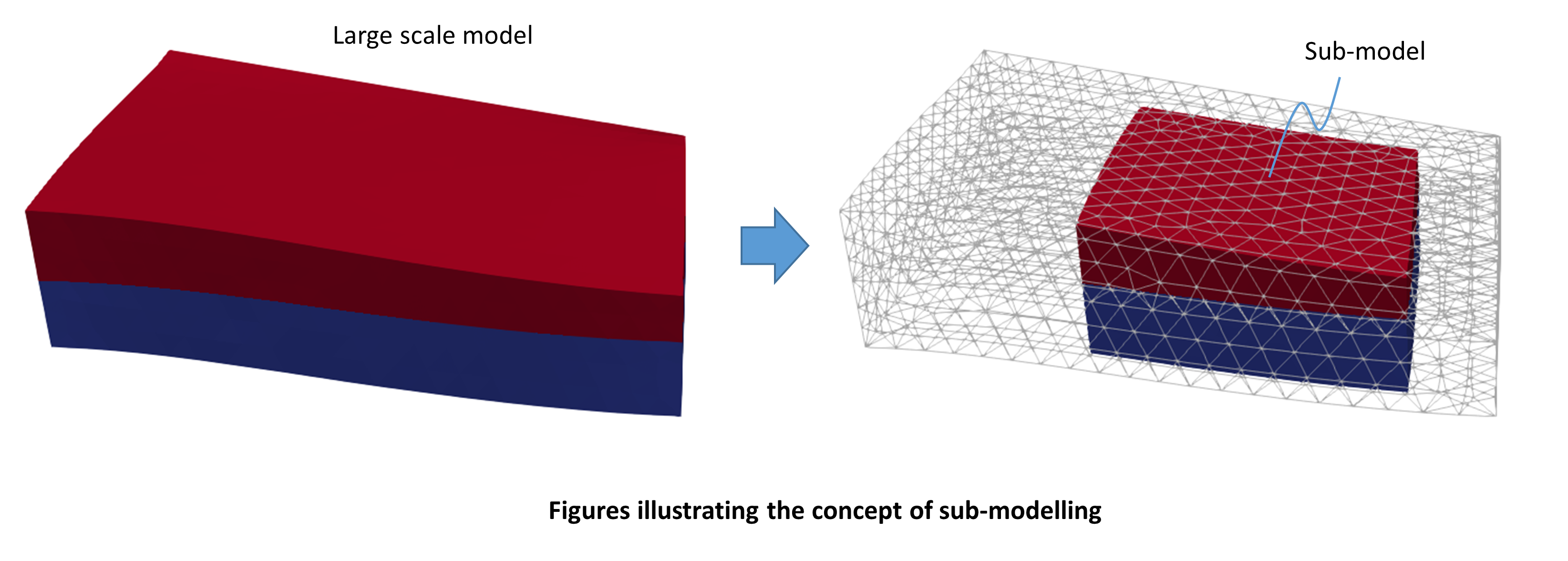
Overview of Sub-modelling Workflow
The concept of sub-modelling refers to perform the modelling of a domain located within a larger scale model. The sub-model usually provides higher resolution of an area of interest. The large scale model is used to obtain the boundary conditions (displacements, pore pressure, temperature, etc) for the sub-model. ParaGeo offers the possibility of performing sub-modelling by adopting the following workflow:
Step 1: Large scale model
During the first step the large scale model should be defined and the simulation should be performed. The results will be used to extract the boundary conditions in later steps. The output of a restart file at the end of the simulation is compulsory.
Step 2: Sub-model creation
In the second step the domain (geometry) of the sub-model should be defined in a datafile. Note that the definition of geometry sets corresponding to the boundaries that will be exported is compulsory. The datafile should contain the minimum data required to run and a single Control_data with the Maximum_number_time_steps set to 1 (we are not interested in performing any simulation at this stage, just to create the sub-model domain). The data structure Boundary_export is used after the Control_data in order to export spatial grids that will define the sub-model boundaries. The generated spatial grids contain the node numbers and coordinates that define each boundary geometry. Each spatial grid is named as: filename_geometrysetname.spat where filename corresponds to the name defined in the Boundary_export data structure and geometrysetname is the name of the geometry set corresponding to such boundary.
Step 3: Extract the boundary conditions for the submodel
In the third step the boundary conditions for the sub-model are extracted from the large scale model using the boundary spatial grids created in step 2 to define the location where the large scale model results are going to be read. A datafile is defined which should contain a restart_read_data structure pointing to the restart file generated after termination of the simulation of the large scale model. Such restart file contains information regarding the plot file names outputted with the results of the large scale model. The data structure Include must be used to read each of the boundary geometry spatial grids. The data structure Spatial_grid_output is then used to output a spatial grid for each included boundary with the variables required to define the boundary conditions for the sub-model.
Step 4: Sub-model simulation
During the last step of the workflow a datafile for the simulation of the sub-model is defined. This datafile should contain the same geometry data defined during Step 2 (via definition of nodal_data, Geometry_line, etc.) and the boundary conditions extracted in Step 3. The data structure Include is used to read the .spat file with the boundary conditions and the Spatial_boundary data structure is used to state which components of the model (displacements in x, y and z; pore pressure; temperature) will be prescribed using the grids within the read .spat file.

