Case 2 Case with adhesion
The data files for the project are in directory: Cont_001\Exercises\Case 2\Data. Look for ! TODO text in the datafile and follow the instructions.
In this tutorial exercise adhesion in the contact will be added. To add adhesion the Contact_property and Contact_set should be modified as shown below. In order to observe its effects a vertical upward displacement on the top surface of the top Block will be defined.
Only the key differences relative to Case01 are discussed below.
Contact_property
Data File |
|
* Contact_property NUM=1 ! ---------------------------------------- Name "Block_friction" Compression_model 1 Compression_properties IDM=1 /"Normal Penalty"/ 500 Tangential_model 2 Tangential_properties IDM=2 /"Tangential Penalty"/ 1000 /"Friction coefficient"/ 0.5 Adhesion_model 1 Adhesion_properties IDM=1 /"Normal Penalty"/ 500
|
1The compression and tangential models/properties are left unchanged. 2The elastic adhesion model is selected (model 1). 3The adhesion normal penalty stiffness is set to 500 MPa.
|
Load data
Data File |
|
* Global_loads NUM=2 ! --------------------------------- Prescribed_displacement IDM=3 JDM=1 /Set1/ 0 0 1 Pres_displacement_geom_set IDM=1 "Top_Block" Pres_displacement_geom_ass IDM=1 1
* Time_curve_data NUM=2 ! --------------------------------- Time_curve IDM=3 0.0 1.0 2.0 Load_factor IDM=3 0.0 -0.05 0.1
* Load_case_control_data ! --------------------------------- Loadcases IDM=2 1 2 Active_load_flags IDM=2 0 2
|
1The time curve for load 2 is modified in such a way that: a.From t=0 to t=1 Ma there is vertical downward compression as in the previous example b.From t=1 to t=2 Ma there is vertical extension (pulling up the top block). 2Load case 1 (lateral displacement) is deactivated in Load_case_control_data.
|
| Results |
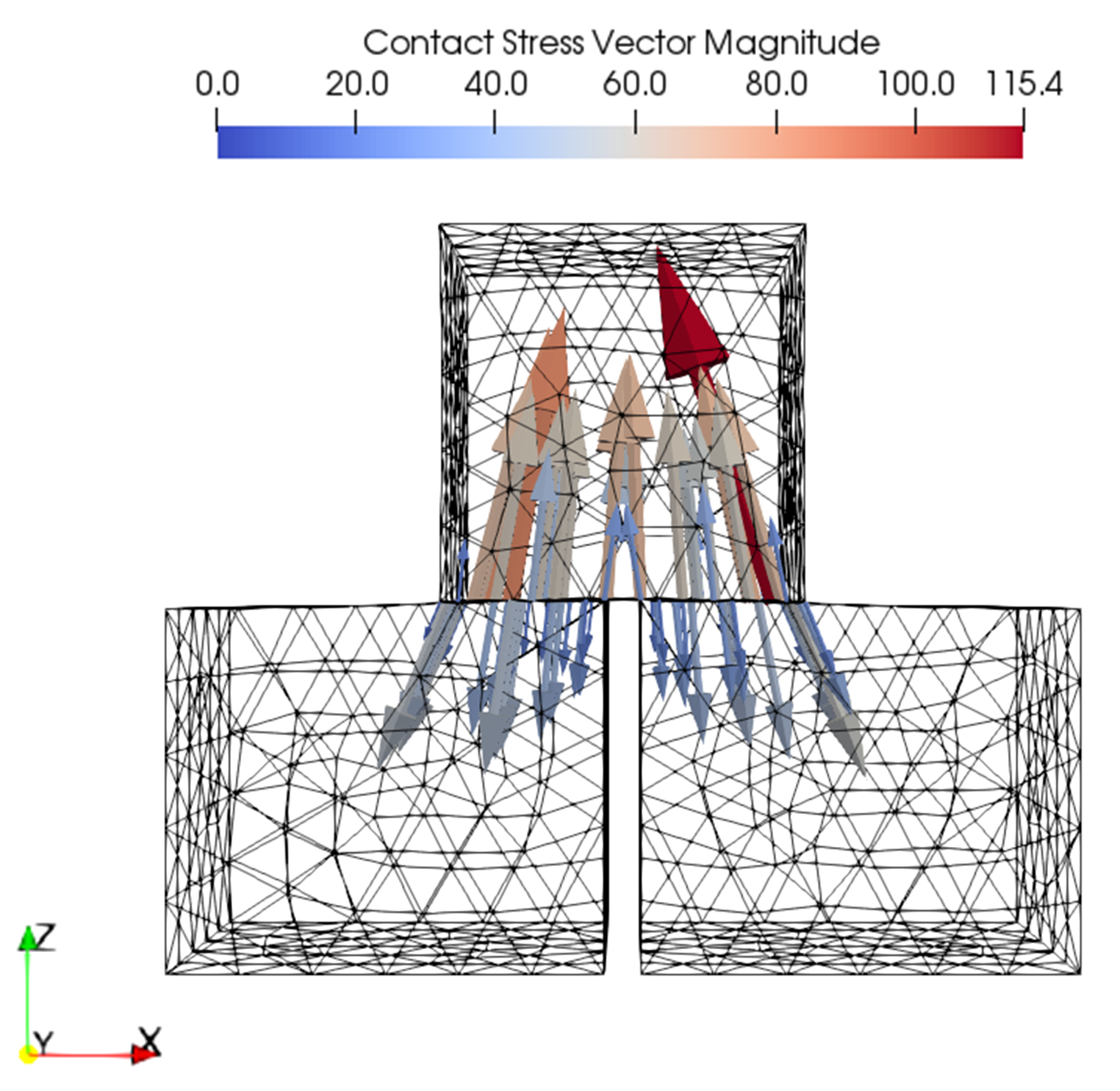
The result files for the project are in directory: Cont_001\Exercises\Case 2\Results. Note how the adhesion prevents the top cube to separate from the base prisms.
Glyph plot of contact stress vectors at the end of stage 2
|
After that example you can undertake Case 3 Case with elastic contact

