Case05 Aditional Facies Functionalities

Contents
In the current case additional functionalities for models with Facies distribution is demonstrated. These specialized functionalities include different keywords which allows for:
▪Deactivation of the flow field for a given facies. The facies boundaries are treated then as non-flow boundaries.
▪Application of permeability multipliers on a facies basis.
▪Deactivation of thermal advection on a facies basis.
In order to facilitate highlighting of the effect in using these specialized functionalities on the pressure field the facies distribution for Formations 01, 02 and 03 is modified relative to Case02 so that all cells in Formations 01 and 02 are assigned facies 3 whereas all cells in Formation03 are assigned facies 4 as shown in the figure below. Note that the .spat files containing the spatial grids used to define the facies distribution have been appended Case02 or Case05 in the file name depending on whether the original or a modified file relative to Case02 is used.
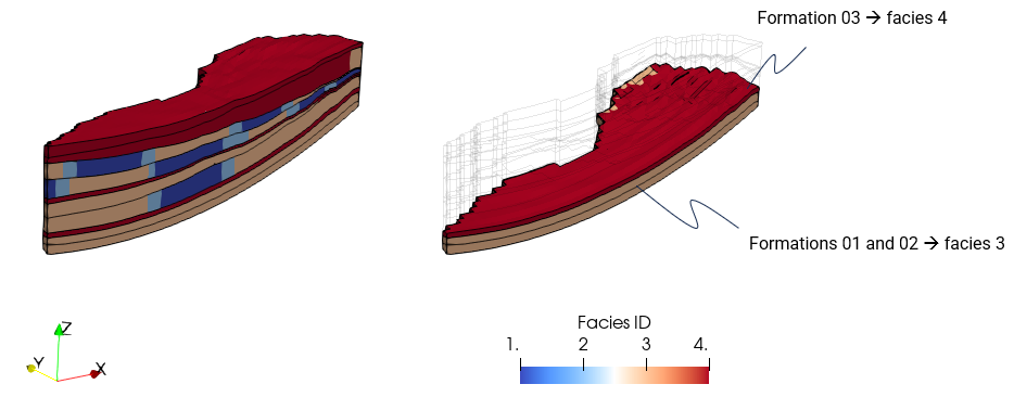
Facies distribution considered in the cases presented here
The cases provided are:
•Geol_002b_Case05a: Standard reference case that does not use any of the specialized facies functionalities beyond facies distribution.
•Geol_002b_Case05b: Case in which the flow field is deactivated for facies 4.
•Geol_002b_Case05c: Case in which permeability multipliers are used to decrease permeability in facies 2 by two orders of magnitude and increase permeability in facies 4 by one order of magnitude.
•Geol_002b_Case05d: Case in which the thermal advection flag is defined on a facies basis. Note that it is not straightforward to highlight the effect of such functionality in the current model. Consequently a column model with a prescribed fluid flow in the base (in addition to the heat flow) will be used instead. A single facies is considered for simplicity. The geometry at the end of the simulation with schematic boundary conditions is shown in the figure below. Two cases will be presented:
▪Case05d1 with the advection terms active.
▪Case05d2 with the advection deactivated.
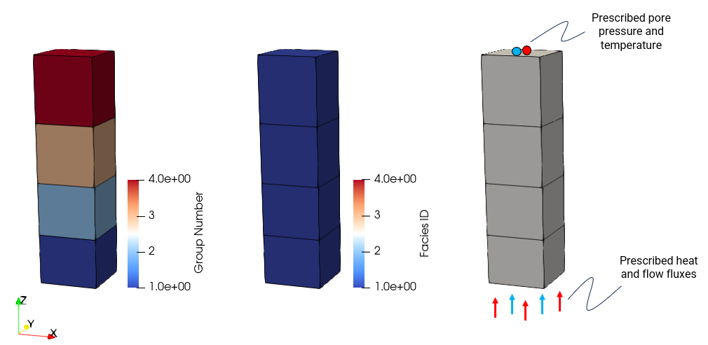
Geometry at the end of simulation with groups, Facies and boundary conditions for Cases 05d1 and 05d2.
The files for all the cases are provided in Geol_002b\Case05\Data. Below only the key data relevant to the additional Facies modelling is shown.
Cases 05a, 05b and 05c
Case05a
Case05b
Case05c
|
Cases 05d
Cases 05d1 and 05d2 adopt a depositional column geometry in order to facilitate demonstration of the effect of the advection terms on the temperature field. The boundary conditions consider a prescribed temperature and pore pressure at the top surface and prescribed fluid and heat fluxes at the base of the column. Deposition of 3 formations is considered but not discussed here.
Flow and Heat boundary conditions
Case05d1
Case05d1
|
Results
A small selection of results are provided in Geol_002b\Case05\Results.
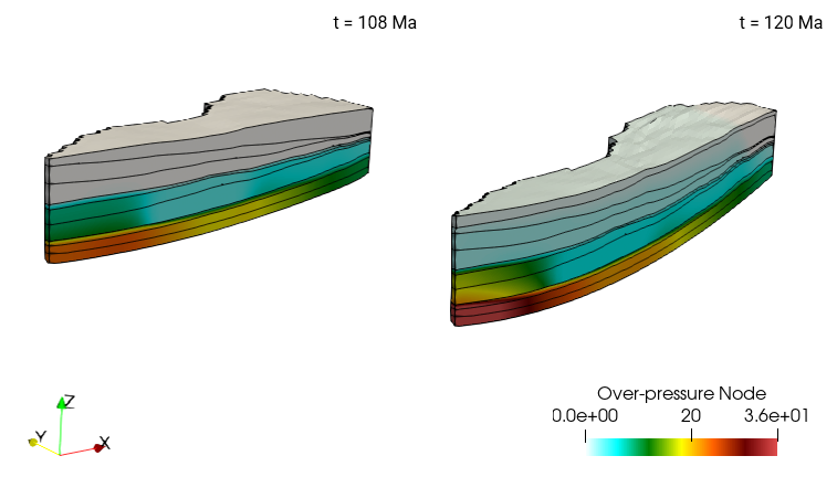
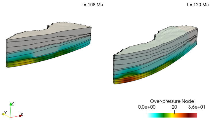
The overpressure distribution in the last 2 stages for Case05a is shown in the picture below. Note that there is relatively large overpressure due to the extensive low permeability layers deposited across the model (Facies 4 and 3 are considered 100% shale and 80% shale with 20% sandstone respectively).
Results for Case05a (standard reference case). V.E. = 3
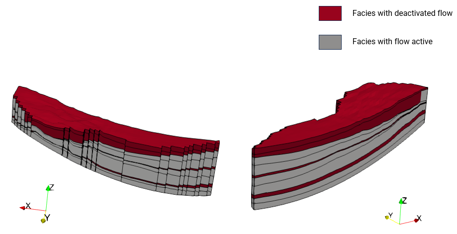
The figure below shows the distribution of facies with deactivated flow (Facies 4) in Case05b. As can be observed that there are 3 effective seals that cover most (or all) of the model surface. Note that even though in Case05a these are low permeability facies, in this Case05b, the overpressure is expected to be larger as the material becomes a perfect seal from its deposition.
Figure showing the active and inactive flow regions in the final geometry for Case05b. V.E. = 3
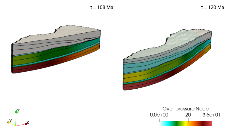
In the figure below overpressure distribution in the last 2 stages for Case05b is shown. As can be seen the overpressure in all the formations is larger than that in Case05a as for this Case05b, Facies 4 behaves as a perfect seal from deposition, impeding any flow across such sediment.
Results for Case05b (case in which flow field is deactivated for Facies 4). V.E. = 3
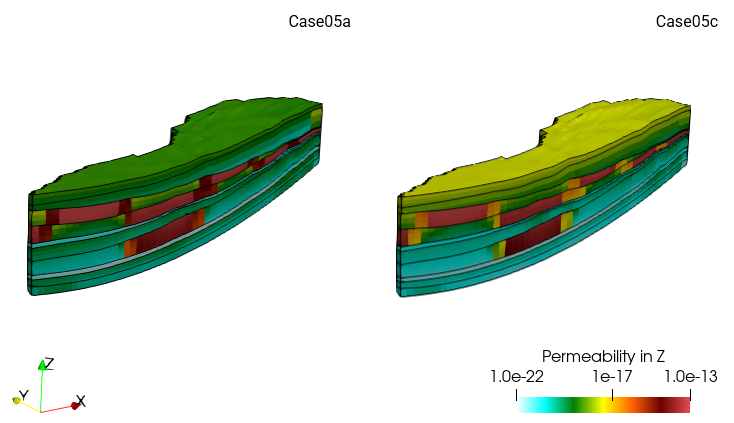
In the figure below a comparison of the vertical permeability distribution for Cases 05a and 05c is presented. Note the larger permeability in Facies 4 (which, as mentioned above, is deposited in several layers across most or the entire model surface). Consequently in this case the predicted overpressure magnitude is expected to be lower compared to the two previous cases. Note also the lower permeability in Facies 2 which is located at the edges of each sand channel section. This is expected to have a rather limited impact due to the limited presence of such facies in the model and its structural distribution which is only laterally bounding the high perm sand channels.
Comparison of vertical permeability distribution for cases05a (standard reference case) and Case05c (case with permeability multipliers). V.E. = 3
As expected, the figure below shows that the overpressure predicted in Case05c is of smaller magnitude than in the previous cases due to the imposed increase by 1 order of magnitude in Facies 4 permeability which exerts a first order control on the overpressure distribution in the model.
Results for Case05c (case with permeability multipliers). V.E. = 3
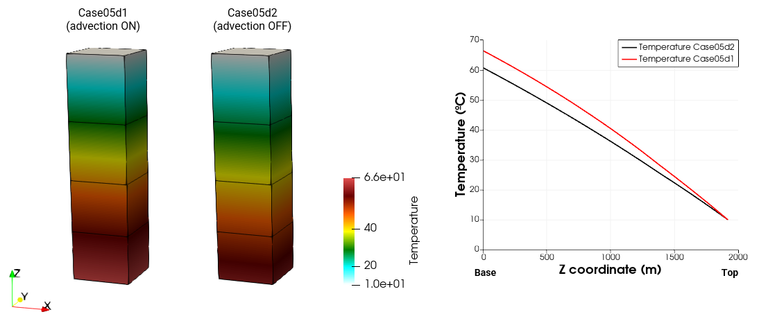
In order to demonstrate the impact of advection in the temperature solution in a clear manner, a depositional column model is used. This allows for the simplification of the thermal and fluid flow pathways as well as allowing appropriate boundary conditions to make the contribution of advection significant in the solution. To this end we have imposed an arbitrary fluid flow flux at the base to enhance flow velocity along the column. In the figure below it can be seen that the contribution of advection resulted in an increased overall temperature along the column. This is because of the role of advection in transporting heat to upper parts of the column combined with the fixed top temperature boundary condition, leading to a larger accumulation of heat at steady state conditions as can be seen in Case05d1 that considers advection.
Comparison of temperature distribution in a depositional column with (05d1) and without (05d2) thermal advection
|