Gmsh_002 Conversion to ParaGeo
In this tutorial page the conversion from the exported mesh to ParaGeo format is discussed. The file can be found in ParaGeo Tutorials/Gmsh_002/02_Conversion/Data/M2G_Gmsh_002.inp
Before discussing the conversion data file an edit to the mesh file exported from Gmsh is required. This consists on making sure that the line below *HEADING command (Line 2) does not exceed 120 characters (otherwise the code will return an error upon conversion). Alternatively lines 1 and 2 from the mesh file (*HEADING command and the defined heading) may be completely removed.
The Conversion Data File
The conversion data file is an .inp file using supported Abaqus style syntax. For more information on the supported keywords and their corresponding options see ParaGeo Abaqus Style Reference Manual . Note that only most relevant data to the present case will be discussed here.
Conversion options
Code |
|
*PARAGEO CONVERSION, TYPE=GEOMETRY, PARAGEO FILE=Ex_008, SUB-DIRECTORY=Conversion *CONVERSION OUTPUT, LEVEL=2, GEOMETRY=YES, MESH=YES
*HEADING Convert Mesh 2 Geomtry with contact at shared interfaces
*UNITS, STRESS=Pa, LENGTH=m, TIME=s, TEMPERATURE=Celsius
|
•Conversion is set as TYPE=GEOMETRY so full generation of the geometry including all geometry entities will be generated (including geometry entities that are not within geometry sets) •File name and subdirectory for output files are defined •Output of a geometry and mesh plot files is requested
|
NSET type definition
Definition of the NSET type for each converted NSET is compulsory
Code |
|
*NSET TYPE Base, Surface South, Surface (...) Underburden, Surface
Overburden_Vol, Volume Caprock3_Vol, Volume (...) Underburden_Vol, Volume
|
•Keyword *NSET TYPE is used to define the type of NSET (LIne, SUrface, Volume) for each NSET in the mesh file. This is compulsory. •Each NSET will be converted to its equivalent Geometry_set data structure •Note that conversion of Volume NSETS is not currently supported and are just ignored. |
Definition of fault and contact data
Note that the mesh was exported unsplit at the fault (there is a single fault surface) and it is going to be split during conversion by definition of *FAULT data set as TYPE=SINGLE
Code |
|
*FAULT, NAME=Fault, TYPE=SINGLE, CONTACT PROPERTY=Fault01, CONTACT SET=All, INTERACTION=All Fault
*CONTACT SET, NAME=All, PROPERTY=Fault01, FREQUENCY=1000 Fault
*CONTACT PROPERTY, NAME=Fault01 *NORMAL, PENALTY=10000E6, TYPE=CONSTANT *TANGENTIAL, PENALTY=10000E6, TYPE=COULOMB 0.2
|
•Definition of *FAULT keyword set with the option TYPE=SINGLE is compulsory for split the fault in hangingwall and footwall surfaces. This together with specification of the geometry set to be split ("Fault" in this case) comprise the minimal data required to perform the split. •In the present case contact data is also defined and assigned to the fault |
Definition of ParaGeo groups
Definition of the volumes to be converted to ParaGeo groups is performed using the *SOLID SECTION keyword.
Code |
|
*SOLID SECTION, ELSET=Volume7, MATERIAL=Underburden *SOLID SECTION, ELSET=Volume16, MATERIAL=Caprock1 *SOLID SECTION, ELSET=Volume17, MATERIAL=Caprock1 *SOLID SECTION, ELSET=Volume12, MATERIAL=Caprock2 *SOLID SECTION, ELSET=Volume13, MATERIAL=Caprock2 *SOLID SECTION, ELSET=Volume8, MATERIAL=Caprock3 *SOLID SECTION, ELSET=Volume9, MATERIAL=Caprock3 *SOLID SECTION, ELSET=Volume14, MATERIAL=Reservoir1 *SOLID SECTION, ELSET=Volume15, MATERIAL=Reservoir1 *SOLID SECTION, ELSET=Volume10, MATERIAL=Reservoir2 *SOLID SECTION, ELSET=Volume11, MATERIAL=Reservoir2 *SOLID SECTION, ELSET=Volume1, MATERIAL=Overburden
|
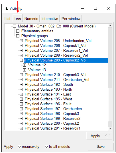
•Note that all volumes from the mesh need to be assigned into a *SOLID SECTION via the option ELSET. Note that such specified ELSET must corresponds to the ELSET name defined in *ELEMENT keywords from the mesh file (e.g. *ELEMENT, type=C3D4, ELSET=Volume1 ) NOT in the names defined in *ELSET keywords. •By default the *ELEMENT data in the exported file is named according to the volume number in Gmsh. Thus, those can be easily identified if Physical groups for each formation were previously defined by clicking on the top menu Tools/Visibility and then selecting the "Tree" tab. From there we can visualise the volume numbers in each formation as shown in the figure below.
View of the visibility window
•Note also that each *SOLID SECTION will be converted to its equivalent ParaGeo Group_data data structure. Consequently edit of the data after conversion will be required in order to assign the correct volumes into the corresponding groups (one group per formation). In order to facilitate that task each solid section is assigned a material name corresponding to its formation (note that volumes will be renumbered during conversion)
|
In order to run the conversion the mesh file exported from Gmsh must be placed into the same folder as the conversion datafile and ParaGeo must be executed specifying the conversion data file including the .inp extension (e.g. in the command prompt write "parageo M2G_Gmsh_002.inp").
The key output results include:
•Ex_008.geo a binary geometry file in ParaGeo format containing the geometry, mesh and all the converted data structures. Note that this will be required to be edited (in HDFView for example)
•Ex_008.GeoSumm summary file in ASCII format of the data stored within the .geo file
•Ex_008.geometry a ParaGeo datafile containing the Group_data and Geometry_set data structures of the converted geometry
•Ex_008.contact a ParaGeo datafile containing the Fault_data and the contact data structures
In addition to those a mesh and a geometry plot file have been output facilitating visualisation in ParaView.
Required edits to the generated data
As previously mentioned, few edits are required to the generated data in order to obtain a geometry properly defined for usage in an analysis (i.e. because the number of groups is not correct). Those edits are described below.
Clean up of the .geo file
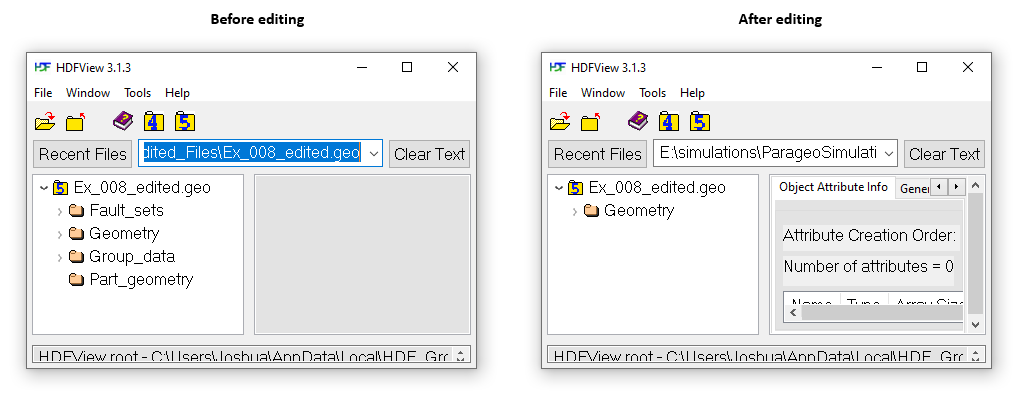
The .geo file must be edited in HDFView. All data structures apart from "Geometry" must be deleted as shown in the picture below. The resulting file will have a .geo file with only geometry and mesh data being defined (the remaining data will be defined in the ParaGeo datafile). Note that in order to be able to edit the .geo file you must ensure that the file has been opened in Read/Write mode by HDFView. You can do that by selecting the .geo file name in the folder structure within HDFView then do a mouse left click and select Reload File As / Read/Write.

View of data structures in the .geo file before and after edit in HDFView
Edit of the .geometry file
The Ex_008.geometry file is edited to correct the group data definition. The previously assigned material names facilitate identification of all the volume numbers that must be included into a given ParaGeo group (note that volumes were automatically renumbered during conversion to the smallest consecutive numbers possible.
Code |
|
! Original * Group_control_data ! ---------------------------------------- Group_numbers IDM=12 1 2 3 4 5 6 7 8 9 10 11 12 Active_geomechanical_groups IDM=12 1 1 1 1 1 1 1 1 1 1 1 1
! Edited * Group_control_data ! ---------------------------------------- Group_numbers IDM=7 1 2 3 4 5 6 7 Active_geomechanical_groups IDM=7 1 1 1 1 1 1 1
|
•Original (top) and edited (bottom) Group_control_data structures are shown. As the target geometry has 7 formations only 7 groups will be defined.
|
Code |
|
! Original * Group_data NUM=3 ! ---------------------------------------- Group_name "Volume8" Element_type "Tet4v" Material_name "Caprock3" Porous_flow_type 5 Volumes IDM=1 3 Geometry_set "Volume8" Average_pressure_flag 0
* Group_data NUM=4 ! ---------------------------------------- Group_name "Volume9" Element_type "Tet4v" Material_name "Caprock3" Porous_flow_type 5 Volumes IDM=1 4 Geometry_set "Volume9" Average_pressure_flag 0
! Edited * Group_data NUM=3 ! ---------------------------------------- Group_name "Caprock3" Element_type "Tet4v" Material_name "Caprock3" Porous_flow_type 5 Volumes IDM=2 3 4
|
•Original (top) and edited (bottom) Group_data structures for the Caprock3 formation are shown as an example. •Caprock3 is defined by two volumes (one at each side of the fault). It can be seen that the original data shows that groups 3 and 4 have assigned material named "Caprock3". This is because we conveniently assigned material names to the solid sections that would facilitate identification of each formation volumes after renumbering. Hence we define the edited Group_data accordingly. •Note that the assigned material name may be modified as well (e.g. all caprocks may be assigned a material named Shale).
|

