Overview of creep models

Contents
The two creep models currently available may be used to consider creep for an elastoplastic or poroelastoplastic material. Currently their usage is limited to working in conjunction with the SR3 plasticity model (SR4 model not available at present). So before presenting the creep laws available a short review of the SR3 model highlighting the main differences with the SR4 model is provided.
The SR3 model
As opposed to the SR4 model, the yield and flow potential surfaces for the SR3 model are defined via a single equation each (which are the same defining the shear side for the SR4 surfaces). Such equations are:
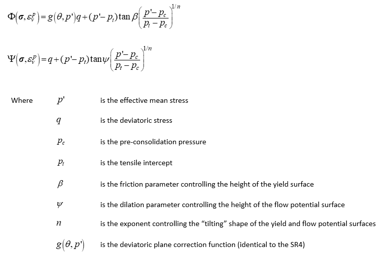
It is noted that a key difference with the SR4 model (in addition to the shape of the yield surface which is not elliptical in the cap side) is that the flow potential surface shape is defined with the same exponent n than the yield surface. Thus in this model the critical state can only be located on the peak q value of the yield surface. As the deviatoric plane correction function is identical to the SR4 one it will not be described here (see Mat_001 SR4 model overview).
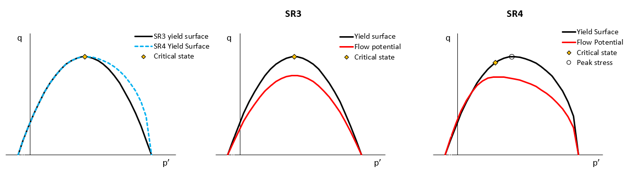
Comparison of yield surfaces for SR3 and SR4 models for the same material parameters (left), SR3 yield and flow potential surfaces (centre), SR4 yield and flow potential surfaces for a flow potential exponent m lower than the yield exponent n, m < n (right)
The SR3 model with creep
Both creep models described here (power law and power law with accelerated creep for deviatoric stress) assume that when loading occurs at a fast rate, the stress path may pass through the yield surface because the short time frame over which the loading occurs does not enable plastic strain nor hardening to fully develop. This implies that the yield surface cannot expand at a rate consistent with the evolving stress path. Thus this would result in the stress state lying outside the yield surface, but because such state is not valid, the model considers that the stress state lies on an "apparent" yield surface which is larger in size than the actual yield surface (the "apparent" yield surface is an expanded version of the actual yield surface). This means that the apparent strength of the material increases with loading rate, which is consistent with the concept of creep. Then if loading stops, creep would occur resulting in both:
1.development of creep strain leading to hardening (expansion of the actual yield surface)
2.stress reduction with the stress path moving towards the actual yield surface
Both processes would occur until the stress state sits on the actual yield surface what would stop further creep.
Thus when combined with creep, the function defining the yield surface in the p' - q space for the SR3 model is modified so that is formulated in terms of the apparent pre-consolidation pressure ![]() and apparent tensile intercept
and apparent tensile intercept ![]() :
:
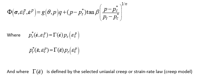
From the equations above it is noted then that the function ![]() defines the ratio of the size between the apparent and the actual yield surfaces. Such function depends on the adopted creep model (e.g. power law or power law with accelerated creep for deviatoric stress) which will be defined below.
defines the ratio of the size between the apparent and the actual yield surfaces. Such function depends on the adopted creep model (e.g. power law or power law with accelerated creep for deviatoric stress) which will be defined below.
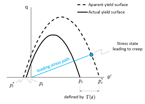
Schematic representation of the actual and apparent yield surfaces
The flow rule for creep is formulated so that the flow direction is normalized and the magnitude of the plastic strain increment ![]() is consistent with the scalar creep strain increment
is consistent with the scalar creep strain increment ![]() as follows:
as follows:
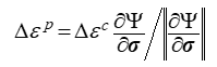
Then the available creep laws defining the relationship between ![]() and
and ![]() are illustrated below.
are illustrated below.
Power law creep model
The power law creep model is defined by the following equation:
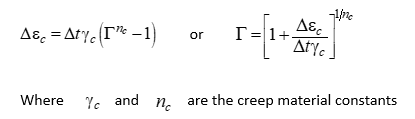
This model and the effect of the material parameters will be discussed in Case01.
Power law creep model with accelerated creep for high deviatoric stress
The power law creep model with accelerated creep for high deviatoric stress is defined by the following equation:
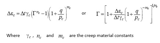
From the equations it can be seen that this model is identical to the power law creep model for hydrostatic loading (q = 0) but the creep rate / amount of creep strain in a given time frame is increased as q increases. This model and the effect of its material parameters will be discussed in Case02.