Case3 Definition and Output of a Reference Set


The data files for the project are in directory: SpatVar_002\Exercises\Case 3\Data. Look for ! TODO  text in the datafile and follow the instructions.


Case3 example shows how to define a Reference_set_data structure in order to set a reference state for the specified variables and.

1.Be able to plot them in ParaView

2.Output them as a Spatial Grid


The reference set will be defined after gravity application so that the specified variables state will be stored and the change  due to the surface load applied on the second stage is going to be output.


Reference_set_data

Data File


* Reference_set_data    NUM=1

! ---------------------------------

 Name          "Complete_domain"

 Groups                IDM=1

   "Sandstone"

 Element_variables       IDM=5        

  "Strs_xx"  

 "Strs_yy"  

 "Strs_xy"

  "Press"    

 "Efstrs"

 Output_reference         0  

 Output_change            1  


1Reference_set_data data structure is defined

2The name of the reference set is set to "Complete_domain"

3Groups with that reference set are listed. In the current example only Sandstone group is present.

4The Element_variables to be referenced are listed. They comprise Stress in X and Y directions, Shear stress in XY plane, Effective Mean Stress (Press) and deviatoric stress (Efstrs).

5Output_reference is set to 0  so that the stored values for the referenced variables are not output as separate variables (note that the reference state coincides with the end of the first stage where a plot file is available, so output reference is not required).

6Output_change is set to 1 so that the change in the referenced variables between the referenced state and the current state is output.


The Spatial_grid_output is defined after the second Control_data so that the exported results correspond to the end of the analysis.


Spatial_grid_output

Data File


* Spatial_grid_output  NUM=1

! ---------------------------------

 Name               "Complete_domain"

 Reference_sets                 IDM=1

   "Complete_domain"

 File_name               "OutputGrid"

 Grid_name_flag                    1  

 Geometry_entity_flag              0  


1The name of the exported grid is set to "Complete_domain". Note that even though the reference set was named "Complete_domain" a name for the exported grid may be defined (which may be different to the reference set name). If not defined the exported grid will be named with a generic name "Spat_grid".

2Reference set named "Complete_domain" is assigned to export it as a grid. Note that similarly to Case1 the grid type will be "Group" (ParaGeo Mesh grid on a group by group basis)

3File name is defined as "OutputGrid". Because Grid_name_flag is set to 1 the exported file name will be "OutputGrid_Complete_domain.spat"

4Geometry_entity_flag is set to 0 so geometry entities at each grid point are not output.

5Note that variables are not specified as all variables stored in the reference set will be output.


Results

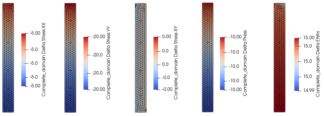
The result files for the project are in directory: SpatVar_002\Exercices\Case3\Results. Note in the figure bellow that the output increment in stress in Y direction is 20 MPa which corresponds to the surface load applied during the second stage.


OutputGrid_Complete_domain.spat

Data File


* Spatial_grid NUM=1

! ----------------------------------------

 Name                     "Complete_domain"

 Type                     "Group"

 Groups                           IDM=1

    "Sandstone"

 Element_variables                IDM=5

    "Strs_xx"

    "Strs_yy"

    "Strs_xy"

    "Press"

    "Efstrs"

 Auto_delete_flag                    0


* Spatial_grid_group               NUM=1

! ----------------------------------------

 Name                     "Sandstone"

 Group_assignment         "Sandstone"

 Grid_name                "Complete_Domain"

 Element_type             "TRIA3"

 Configuration_type       "Current"

 Element_variables                IDM=5

    "Strs_xx"

    "Strs_yy"

    "Strs_xy"

    "Press"

    "Efstrs"

 Topology                         IDM=3   JDM=622

  57    3  111

 110    1  112

    .

    .

    .

 328  367  251

 Node_numbers                     IDM=367

   1    2    3    4    5    6    7    8    9   10

  11   12   13   14   15   16   17   18   19   20

    .

    .

    .

 361  362  363  364  365  366  367

 Coordinates                      IDM=2  JDM=367

   0.00000        0.00000    

   100.000        0.00000    

    .

    .

    .

   49.2221        835.761

 Element_values                   IDM=5  JDM=622

  -5.00000    -20.0000   0.112316E-04   -10.0000    14.9975    

  -5.00035    -20.0014   -0.128645E-04  -10.0007    15.0010    

    .

    .

    .

  -5.00008    -20.0004   -0.604388E-05  -10.0002    15.0001    


1Spatial_grid data is defined.

2Type is set to "Group" (ParaGeo mesh on a group by group basis).

3Groups with grid data are defined. In this case there is only one group named "Sandstone".

4The Element_variables for which the grid contains values are specified.

5Auto_delete_flag = 0 means that grid will be automatically deleted after being used by ParaGeo for any other operation (if loaded to any other ParaGeo model).


6Spatial_grid_group data which contains the grid with variable values for the group "Sandstone" is defined.

7The element type of the grid are Triangles.

8Configuration_type "Current" means that values exported to the grid correspond to values at the time of export (in this case at the end of the analysis).

9The Element_variables for which the grid contains values are specified.

10The topology for all the grid elements is defined. There is a total of 622 elements in the grid with each element being composed of three nodes.

11Node numbers are provided.

12Node coordinates for the 367 nodes are provided. Each row correspond to each node specified in node_numbers following the same order (i.e. row 12 are coordinates for the 12th node specified in Node_numbers, which in this case is node number 12).

13Values at each element for the five specified variables are provided. Each column correspond to the variables specified in Element_variables following the same order. Each row correspond to each element defined in Topology following the same order.

14Note that output values correspond to the change in variables values between the referenced state (after gravity application) and the output time (end of the analysis)


SpatVar_002_Case3_Results

View of the Reference Set Output (change in variables).