Val_003 Plane-Strain Wellbore in Poroelastic Medium (Detournay and Cheng 1988)
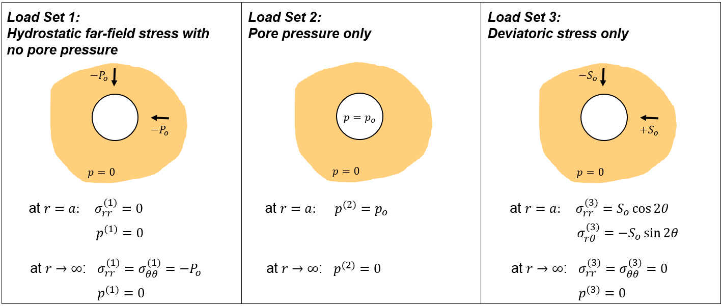
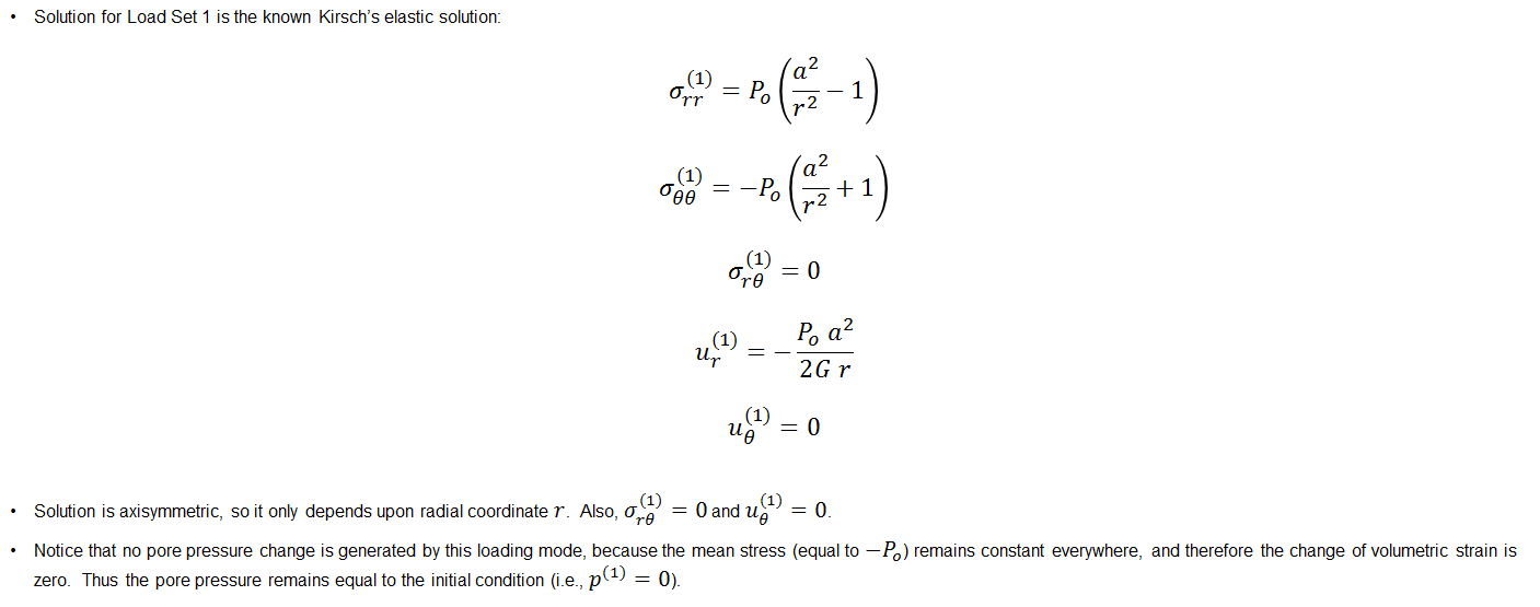
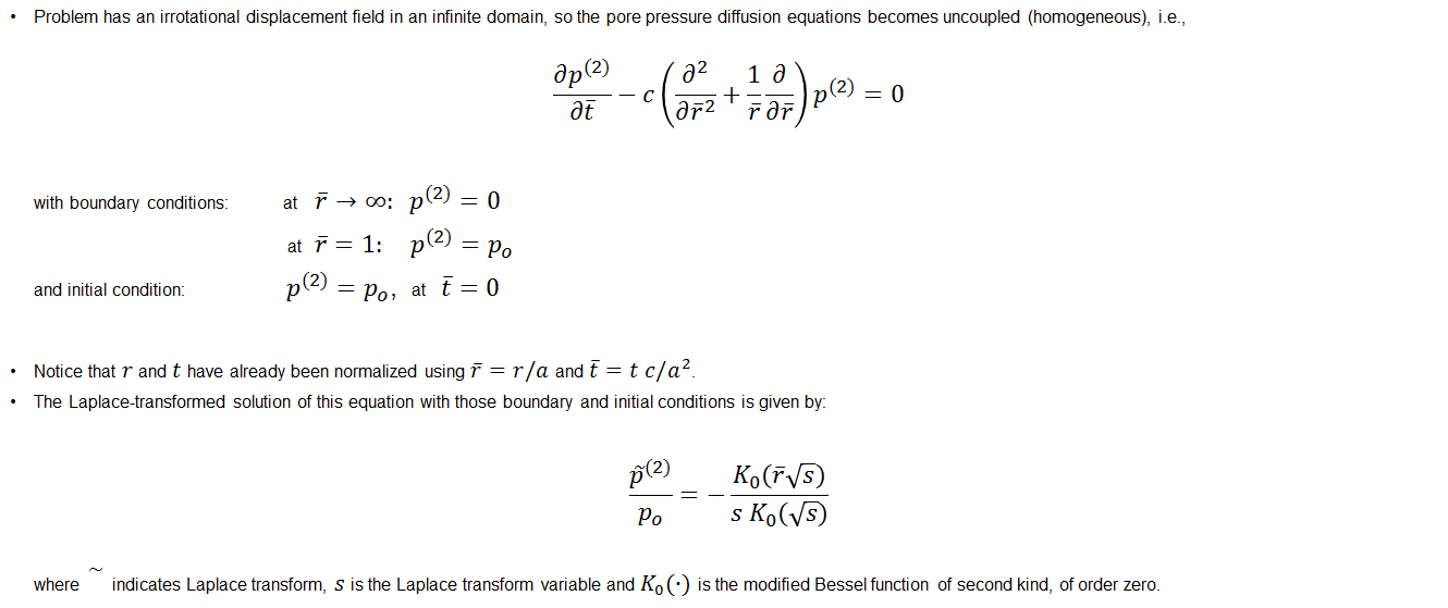
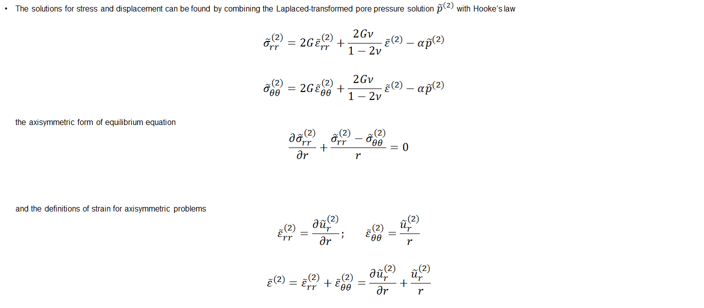
The problem considers a borehole of radius a excavated at time t = 0 on an infinite poroelastic medium under plane strain condition. The internal pressure is 0 and the far-field principal stresses are aligned with x and y axis with σyy > σxx. In the schematic picture below P0 = -0.5 · (σxx+σyy) is the mean horizontal stress and S0 = -0.5 · (σxx-σyy) is the horizontal deviatoric stress. The initial pore pressure is p0.
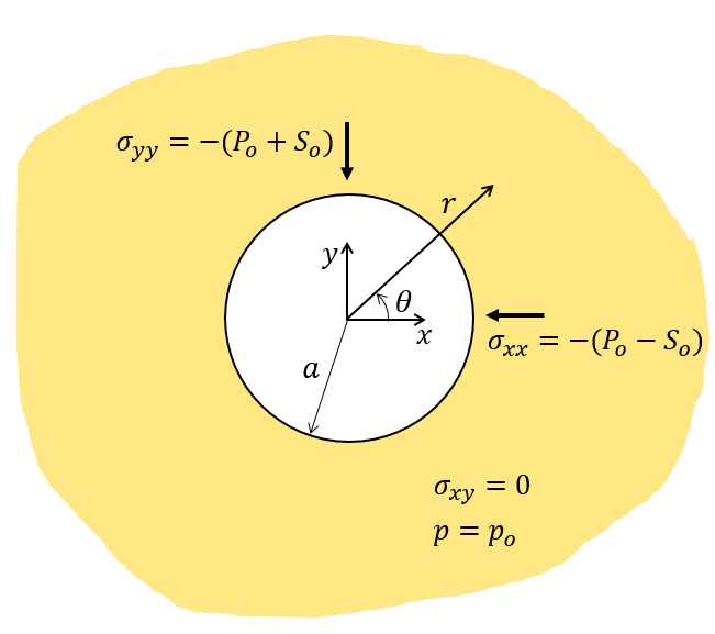
Schematic of problem boundary conditions
In this case the model is set up so that:
•Domain consists of a quarter symmetry borehole model with size length 3 m x 3 m with a hole size of 0.1 m radius discretized into 5120 structured triangular plane strain elements that decrease in size towards the hole.
•Roller boundary conditions are imposed on the symmetry axes.
•Stresses applied on top and side are σyy= 17.237 MPa (2500 psi) and σxx= 13.79 MPa (2000 psi) respectively (P0 = 2250 psi and S0 = 250 psi).
•Initial pore pressure is p0 = 6.8948 MPa (1000 psi).
•Relevant material and fluid properties are:
oE = 10 GPa
oν = 0.25
oΦ = 0.2
oKg = 38 GPa
oKf = 2 GPa
ok = 1·10-15 m2 (c = 9.81·10-9 m/s)
oρw = 1000 Kg/m3
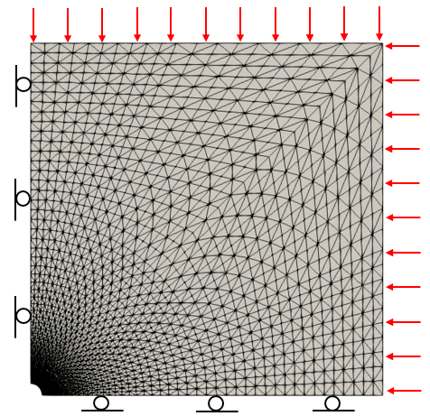
Schematic of model domain
The data file for the model is found in: ParaGeo Examples\Validation\Val_003\Data\Val_003a.dat. (Case Val_003b considers different permeability)
|
| Results |
The result files for the project are in directory: ParaGeo Examples\Validation\Val_003\Results. The Plots Over Line exported from ParaView are provided in CSV format and pasted into Val_003_Wellbore.xlsx sheet. 2 cases are considered; Val_003a and Val_003b with permeabilities of 1·10-18 m2 and 1·10-15 m2 respectively.
and
The results show that ParaGeo calculations match reasonably well the analytical solution:
Results Val_003a (case with k=1·10-18 m2)
Normalized pore pressure (left), normalized radial stress (center) and normalized tangential stress (right) as a function of normalized distance to wellbore center. Results along X axis (0 degrees). ParaGeo results (dots) compared to analytical solution (solid lines). Note that if lines are not seen is because simulation points are superposed.
Normalized pore pressure (left), normalized radial stress (center) and normalized tangential stress (right) as a function of normalized distance to wellbore center. Results along Y axis (90 degrees). ParaGeo results (dots) compared to analytical solution (solid lines). Note that if lines are not seen is because simulation points are superposed.
Results Val_003b (case with k=1·10-15 m2)
Normalized pore pressure (left), normalized radial stress (center) and normalized tangential stress (right) as a function of normalized distance to wellbore center. Results along X axis (0 degrees). ParaGeo results (dots) compared to analytical solution (solid lines). Note that if lines are not seen is because simulation points are superposed.
Normalized pore pressure (left), normalized radial stress (center) and normalized tangential stress (right) as a function of normalized distance to wellbore center. Results along Y axis (90 degrees). ParaGeo results (dots) compared to analytical solution (solid lines). Note that if lines are not seen is because simulation points are superposed.
|
| References |
Cheng, A. H.-D. (2016). Poroelasticity. Springer.
Detournay, E. and Cheng, A. H.-D. (1988). Poroelastic response of a borehole in a non-hydrostatic stress field. Int. J. Rock Mech. Min. Sci. & Geomech. Abstr. 25:171-182.
Detournay, E. and Cheng, A. H.-D. (1993). Fundamentals of poroelasticity, In: Comprehensive Rock Engineering: Principles, Practice and Projects, Hudson, J.A. (ed.). 2:113-171. Pergamon Press.
|


