Ex_008 Well Element
The examples here demonstrate the usage of well elements for different field applications and modelling scenarios.
Tutorial Examples
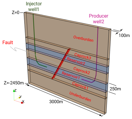
Case 01 - Injection and Production
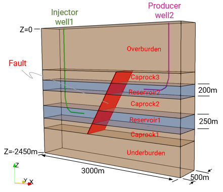
Case 02 - With Contact Advection along Fault
Case01 and Case02 examples demonstrate the usage of well elements in an illustrative THM injection and production models akin to the MEM example MEM_001 Case04 HM Coupled Producer and Injector Wells. It is assumed that the user is familiar with the MEM workflow and data structures demonstrated in MEM_001_Case04. Hence, only the data associated with usage of well elements and thermal data will be described.
|
|
Case 01 Injection and production THM model |
Case 02 Injection and production THM model with contact advection along fault |
Injection and depletion of a reservoir layer via well elements will be simulated. The reservoir is underlain and overlain by shale lithologies. The 250m thick reservoir is at a depth of 1500m below the surface. The model is initialized following a sequence of stages:
Stage 1: Elastic gravity initialization.
Stage 2: Contact release (Initialization).
Stage 3: Constitutive release (Initialization).
Stage 4: Start of well injection ramped up to rate of 5000 m3/day over 10 days.
Stage 5: Start of well production ramped up to rate of 5000 m3/day over 10 days.
Stage 6: Injection and production flow at constant rate of 5000 m3/day simulated over 14 years (5110 days) for Case01 and 84 years (30660 days) for Case02.
Features of the 3D model comprise:
1.THM coupled simulation.
2.Deactivated porous flow in shale layers.
3.Seven material layers with two reservoir layers.
4.Two wells - one injector well and one producer well.
5.Incline fault separating the two wells.
6.Initial hydrostatic pore pressure.
7.Initial depth-dependent spatial temperature gradient.
8.Well injection and production rate of 5000m3/day. Well injection fluid temperature is defined as 30°C.
9.Contact advection along fault (Case02 only).
10.Well definition history (Case02 only).
11.Usage of transient time growth increment in solution control for simulation duration over 14/84 years.
The tables below show the thermal material input data for the shale and reservoir layers and pore/well fluid.
Material Properties
The principal thermal parameters for the shale material layers are:
|
The principal thermal parameters for the reservoir material layers are:
|
Fluid Properties
The principal parameters for the pore and well fluid "water" are:
|
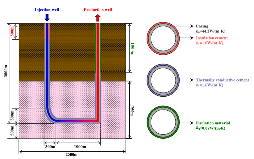
Case 03 - U-Shaped Geothermal Well with Multiple Well Completions
Wellbore heat transmission in U-shaped geothermal wells with multiple well completions in a multi-layered rock model.
|
Case03: Schematic of U-shaped Well Geothermal Production System (adapted from Ref.1) |
Case 04 - Influence of Skin Factor on Well Elements using the Peaceman Model
Application of the Peaceman model on well elements with emphasis on the influence of skin factor.
|
Case04: Example Model Geometry (overlaid with Mesh Definition) |
References
[1] Yuanyuan Ma, Shibin Li, Ligang Zhang, Songze Liu, Ming Wang, Heat extraction performance evaluation of U-shaped well geothermal production system under different well-layout parameters and engineering schemes, Elsevier Renewable Energy 203 (2023) 473 - 484.
|


