Case02 Appropriate Pore Pressure Loading

Contents
The aim of the present case is to demonstrate how the prescribed pore pressure loads (if applicable) must be defined for the different flow types and the results when defined incorrectly. To that end the same initialisation assumptions as in Case01 will be adopted. After initialisation a prescribed pore pressure load to the base of the column is applied to increase the values from hydrostatic value (9.7 MPa) to 18 MPa. Note that:
•For porous flow types 0 (no pores), 1 (dry pores) and 5 (buoyant effective stress) pore pressure loads must not be defined as this would not be physically valid for the corresponding assumptions.
•The treatment of pore pressure loads for porous flow types 2 (drained) and 3 (undrained) is the same, the only difference being that in the undrained analysis the pore pressure generated from volumetric strain is added.
Hence in the present case only porous flow types 2 and 4 will be considered. Firstly we will discuss the case with porous flow type 4 whereby the porous flow field is solved.
Porous flow type 4
In the datafile Ex_013_Case02a_pf4.dat the porous flow field is solved (coupled analysis). Hence in order to increase the pore pressure from hydrostatic values to a distribution such that the pore pressure in the base is 18 MPa:
•In second stage we re-specify Support_data so that pore pressure constraints are specified for the base (via Pore_pressure_codes, Pore_pressure_code_geom_set and Pore_pressure_code_geom_ass). This is required when we want to prescribe pore pressure for the flow field in any geometry entity in the model using Global_loads.
•A Global_loads data structure prescribing pore pressure in the base is defined. The actual pore pressure value will be controlled by the Load_factor in the associated Time_curve_data.
•We can see in the results below that the distribution after the second stage is a linear distribution from 0 MPa at the top (prescribed via Stratigraphy_surface_load) to 18 MPa at the base. The flow field is solved over the whole of the domain from the basal pore pressure loading.
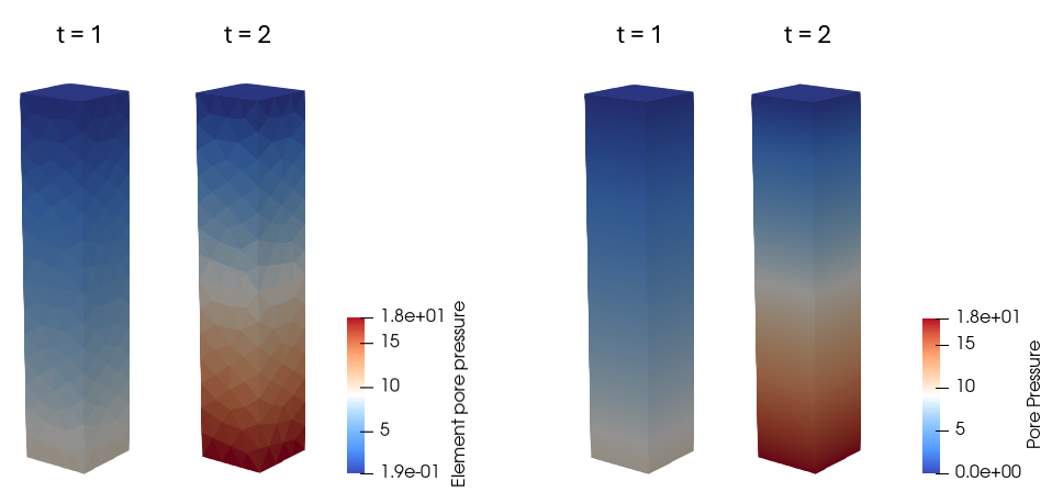
Results after initialisation (t=1) and after application of the pore pressure loading (t=2) for Case02a_pf4
Porous flow type 2
For porous flow type 2 only the mechanical field is solved whereas the pore pressure is prescribed but not solved. If the pore pressure values are not defined it is assumed to be 0. In the datafile Ex_013_Case02a_pf2.dat we demonstrate the result if we attempt to prescribe the pore pressure at the base:
•Because we are using porous flow type 2, during the first stage the hydrostatic pressure distribution is prescribed from Geostatic_data but this distribution is overwritten by any defined pore pressure loading in a subsequent stage. Consequently only those entities with prescribed pore pressure show pore pressure values larger than 0 in the second stage (see results below in which the base is the only location that has pore pressure values larger than 0).
•Note that for porous flow type 2 pore pressure codes and constraints must NOT be defined in Support_data (any pore pressure loading would be element pore pressure for the mechanical field).
•We can see in the results below that the maximum pore pressure value in the elements at the base is 13.5 MPa which differs from the prescribed value of 18 MPa. This is because the basal elements have 3 out of 4 nodes that belong to the "Base" geometry set. Consequently the element pore pressure may be calculated as 18 MPa · 3/4 = 13.5 MPa.
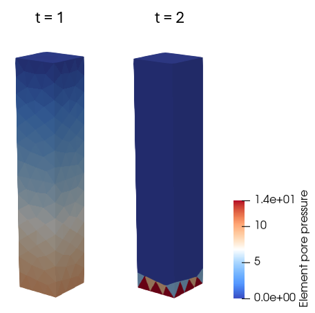
Results after initialisation (t=1) and after application of the pore pressure loading (t=2) for Case02a_pf2
•Note that because in porous flow type 2 any pore pressure values different from 0 have to be specifically prescribed, to achieve a given distribution we need to prescribe the values for every element in the mesh. However Global_loads only allows constant values to be prescribed to the assigned geometry entities (e.g. we may prescribe the same pore pressure value for a given geometry volume as commonly done in wellbore models).
•In Ex_013_Case02b_pf2.dat we demonstrate the appropriate method for prescribing a pore pressure distribution in the model. This is done by reading a Spatial_grid with element pore pressure (Elt_pore variable) values defined for every element in the mesh and applying these values as a loading via Spatial_boundary. The results are shown below.
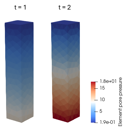
Results after initialisation (t=1) and after application of the pore pressure loading (t=2) for Case02b_pf2
Summary Table of Appropriate Pore Pressure Loading Definition
Porous Flow Type |
Geostatic Pore pressure Initialisation* |
Pore pressure Loading |
Pore pressure Support Constrains |
Notes |
0 |
-- |
-- |
-- |
Element Pore Pressure is 0 |
1 |
-- |
-- |
-- |
Element Pore Pressure is 0 |
2 |
Geostatic (distribution, constant)
|
Global Loads (constant) Spatial boundary (distribution, constant) |
No |
Element Pore Pressure is output If pore pressure is defined via Spatial Boundary Elt_pore variable (element pore pressure for geomechanical field) must be used |
3 |
Geostatic (distribution, constant)
|
Global Loads (constant) Spatial boundary (distribution, constant) |
No |
Element Pore Pressure is output It is uncommon to define pore pressure loading beyond the initial value as all volumetric strain causes undrained pore pressure generation |
4 |
Geostatic (distribution, constant)
|
Global Loads (constant) Spatial boundary (distribution, constant) |
Yes |
Element Pore Pressure and Pore Pressure (nodal) are output If pore pressure is defined via Spatial Boundary Pore_nod variable (nodal pore pressure for flow field) must be used |
5 |
-- |
-- |
-- |
Element Pore Pressure is 0 |
* It should be noted that depending on the type of application/model it is also possible to define the initial pore pressure via Global Loads or Spatial Boundary data. Some workflows may even require it to be defined outside of Geostatic_data (e.g. in mechanical only MEMs like the one presented in MEM_001_Case01 the initial pore pressure distribution must be initialised via Spatial_boundary).