Case01 Assumptions for each Porous Flow Type

Contents
The data files for the current tutorial are provided in ParaGeo_Examples/Ex_013/Case01/Data and the results are in ParaGeo_Examples/Ex_013/Case01/Results. Note that all data files have appended the porous flow type number in the file name (e.g. Ex_013_Case01_pf3.dat would be the data file for porous flow type 3).
All the data files are identical except the assumed porous flow type in each case (and the required extra modifications required for the Porous_flow_type 4 case which considers hydro-mechanical coupling). Those data files encompass data required to achieve gravity initialisation with hydrostatic pore pressure (via Gravity_data and Geostatic_data). The explanation of the assumptions and results for each porous flow type is provided below.
Porous flow type 0 (Non-porous material)
Groups with porous flow type 0 consider non-porous materials (e.g. appropriate for metal casing in wellbore models). Consequently:
•The bulk density for those groups becomes equal to the grain density (2700 kg/m3 in the present case)
•No pore pressure is output (there are no pores to be filled with fluid)
•The column height measured at the deepest element centre (maximum element depth relative to top surface) after the strains from gravity initialisation is 987.76 m
•The vertical effective stress at the base of the column is equal to the total stress, which is:
![]()
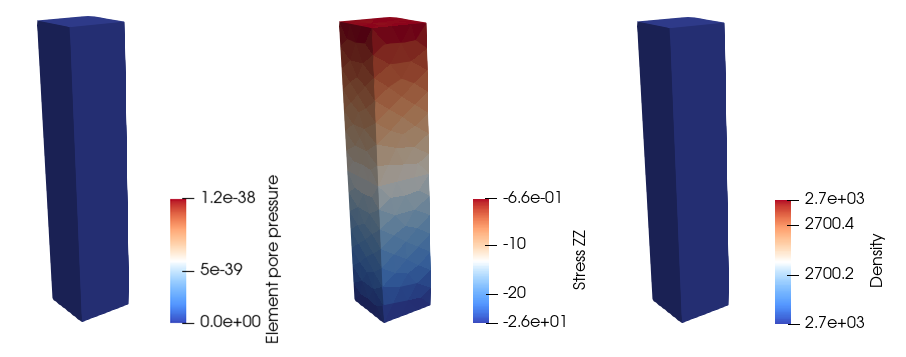
Initialisation results for porous flow type 0
Porous flow type 1 (Dry porous material)
Groups with porous flow type 1 consider dry porous materials. Consequently:
•The bulk density for those groups is the grain density multiplied by 1 minus the porosity which in the present case is:
![]()
•No pore pressure is output (no fluid filling the pores)
•The column height measured at the deepest element centre (maximum element depth relative to top surface) after the strains from gravity initialisation is 988.24 m
•The vertical effective stress at the base of the column is equal to the total stress, which is:
![]()
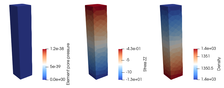
Initialisation results for porous flow type 1
Porous flow type 2 (Drained porous material)
Groups with porous flow type 2 consider drained analysis with prescribed pore pressure (solving mechanical field only). This implies that the pore pressure in any geometry entity may be prescribed contributing to the effective stresses and that volumetric strain does not lead to a pore pressure change. Thus:
•The bulk density for those groups is calculated from the grain and fluid densities taking into account the porosity, which for the present case is:
![]()
•The column height measured at the deepest element centre (maximum element depth relative to top surface) after the strains from gravity initialisation is 988.42 m
•Element pore pressure is output (pore pressure for the mechanical field) and is prescribed to hydrostatic pressure values by Geostatic_data as:
![]()
•The vertical effective stress at the base of the column is:
![]()
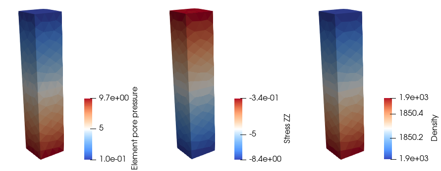
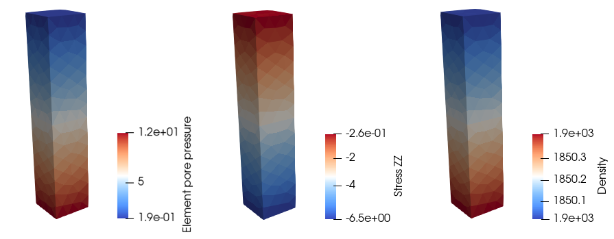
Initialisation results for porous flow type 2
Porous flow type 3 (Undrained porous material)
Groups with porous flow type 3 consider undrained analysis so that all volume strain is assumed to contribute to pore pressure increase (note only mechanical field is being solved). Note that the code allows pore pressure to be prescribed to any geometry entity to which the undrained pore pressure will be added. Thus:
•The bulk density for those groups is calculated from the grain and fluid densities taking into account the porosity, which for the present case is:
![]()
•The column height measured at the deepest element centre (maximum element depth relative to top surface) after the strains from gravity initialisation is 988.49 m
•Element pore pressure is output (pore pressure for the mechanical field). In Geostatic_data hydrostatic values are prescribed which should yield a value of 9.7 MPa at the base of the column. However a value of 11.54 MPa is obtained. This is a result of the extra pore pressure resulting from the undrained assumptions. To validate that, we interrogated the results for element number 359 which is located at the base (note that the calculations are provided in the excel sheet 00_Ex_013_Calculations.xlsx). For this element we first calculate the coupling stiffness (Kc) using the equation below:
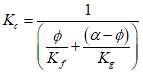
Where Kf and Kg are the fluid and grain stiffness respectively, Ø is the porosity and α is the Biot's constant. In this case the calculated coupling stiffness Kc=3890.65 MPa. The volumetric strain for the element εv= 4.79338·10-4 . Thus we can calculate the extra pore pressure generated by the volumetric strain with undrained assumptions as:
![]()
Hence the output element pore pressure value (11.54 MPa) is consistent with the sum of the expected hydrostatic value (9.67 MPa) and the pore pressure generated via volumetric strain (1.8649 MPa).
•The vertical effective stress at the base of the column is then:
![]()
Initialisation results for porous flow type 3
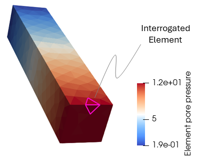
Detail of interrogated element to validate the output pore pressure value
Porous flow type 4 (Porous material with coupling HM assumptions)
Groups with porous flow type 4 consider coupled analysis in which the flow field is solved with the coupling assumptions between mechanical and flow field defined by the Volume_strain_coupling scheme assigned in Couple_control_data. For the present case the coupling scheme has been set to "None" (volumetric strain does not generate pore pressure). The results below show that:
•Because the flow field is solved, in addition to the "Element Pore Pressure" (pore pressure for the mechanical field) the variable "Pore Pressure" is output (nodal pore pressure solved by the flow field).
•The bulk density for those groups is calculated from the grain and fluid densities taking into account the porosity, which for the present case is:
![]()
•The column height (max element depth) after gravity initialisation is 988.42 m
•Because volumetric strain does not contribute to pore pressure generation (Volume_strain_coupling "None") the expected pore pressure values are hydrostatic. We can see that the Element pore pressure is calculated as:
![]()
•Note that the maximum value for "Pore Pressure" is slightly higher than that of "Element Pore Pressure" (9.8 MPa vs 9.7 MPa respectively). This is because "Pore Pressure" variables are calculated at the nodes as opposed to the element centres. The column height taken into account is slightly larger as it considers height from the top surface to the true base of the model. In the present case the true height is 999.68 m, hence the nodal pore pressure is:
![]()
•The vertical effective stress at the base of the column is:
![]()
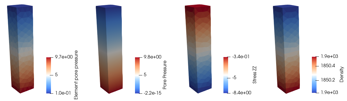
Initialisation results for porous flow type 4. Note that the code outputs pore pressure at nodes (pore pressure for the flow field)
Note that the extra modifications required in the data file for this case (HM coupled case) relative to the other cases (mechanical only cases) were:
1.Activate the porous flow field in Group_control_data
2.Definition of Couple_control_data with Geomechanical and Porous_flow fields as coupled. For the present case the coupling algorithm has been set to "None" (volumetric strain does not generate pore pressure)
3.Definition of appropriate Control_data keywords and options for coupled analysis; i.e.:
a.Solution_algorithm must be set to 4.
b.Initial_time_increment defining the flow step size must be defined.
c.Target_number_time_steps for coupled analysis defines the number of mechanical time steps per each flow step. Note that in mechanical only cases, Target_number_time_steps defines the total target number of mechanical time steps for the stage.
Porous flow type 5 (Porous material with hydrostatic assumptions via buoyant density)
Groups with porous flow type 5 consider hydrostatic effective stress analysis via the calculated buoyant density (note that no pore pressure is defined). Thus:
•Element Pore Pressure is not output because there is no pore pressure present in the analysis
•The buoyant density for the groups is calculated according to ![]() which in the present case is:
which in the present case is:
![]()
•The column height (max element depth) after gravity initialisation is 988.42 m
•The vertical effective stress at the base of the column is:
![]()
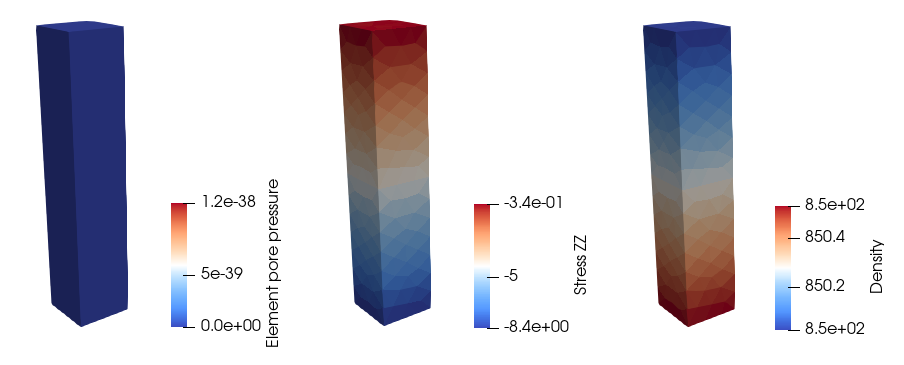
Initialisation results for porous flow type 5