Case02 Slice Model
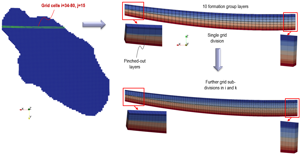
The 3D slice model presented here is extracted from the basin model at the highlighted location in green outline. A full description of the geomechanical restoration and forward simulation for the slice model will not be described - only description of additional data or data different to the Case01 - Column Model is presented here. To this end, it is recommended to familiarise with the Case01 column model before undertaking this example.
Simulation runs on a single 3.6GHz AMD Processor PC for Case02 slice model comprising 5965 nodes, 2899 elements took:
•Restoration - 3 minutes.
•Forward Simulation - 7 minutes.
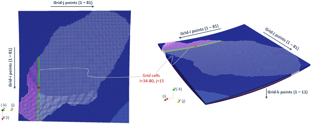
Slice Model located at Grid cells i=34-80, j=15 in Geol_002 Basin Model with 80 x 80 grid cells (1 cell = 1km)
The workflow comprise four main steps:
1Step 01 - Zmap file import and output to ParaView plot file and Abaqus input .inp file.
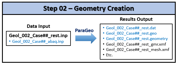
2Step 02 - Conversion of .inp file to suitable ParaGeo geometry (.geo and .geometry) files and data .dat file.
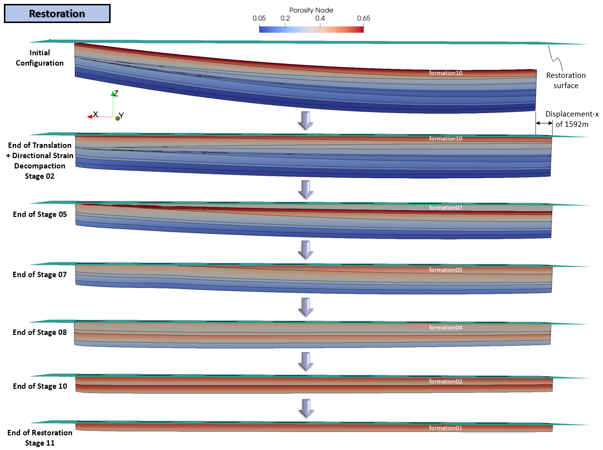
3Step 03 - Geomechanical restoration of the defined 3D geological structure with directional strain decompaction.
4Step 04 - Forward simulation of the sedimentation process (THM modelling).
Each of these steps contains only a description of additional data or data different to the column example in their respective sections following.
The Zmap import data files for the slice model are in : Geol_002\Case02\01 - Zmap import\Data. The key differences in the Step 01 workflow is in the main Zmap import data file Geol_002_Case02_geom.dat.
Workflow Flowchart for Step 01 - Zmap Import
Data File Description
Results
|
The data files for the ParaGeo geometry creation for the slice model are in : Geol_002\Case02\02 - Geometry creation\Data. The key difference in the Step 02 workflow is in the main ParaGeo geometry creation file Geol_002_Case02_rest.inp.
Workflow Flowchart for Step 02 - ParaGeo Geometry Creation Data File Description
Results
|
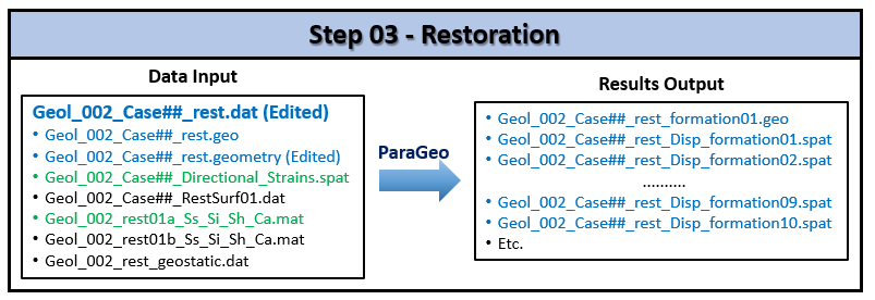
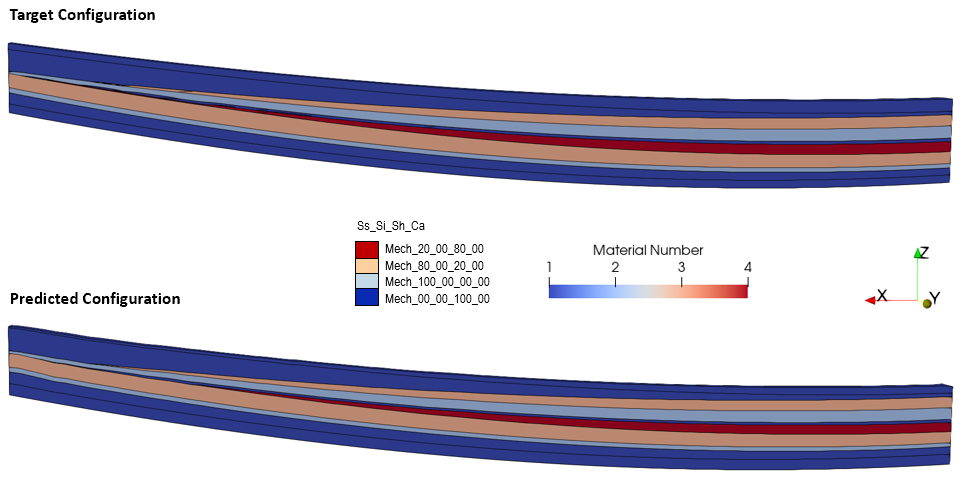
Step 03 involves performing the geomechanical restoration for the slice model with directional strain decompaction as shown in the flowchart below. This involves input of two additional files in the workflow shown in green text: 1Geol_002_rest01a_Ss_Si_Sh_Ca.mat: File containing Material_data defining the mechanical properties and directional strain decompaction. 2Geol_002_Case02_Directional_Strains.spat: File containing the directional strain spatial grid data with 3% strain in XX for the entire slice model.
The restoration data files for the slice model are in: Geol_002\Case02\03 - Restoration\Data.
Workflow Flowchart for Step 03 - Restoration
Initial Slice Model showing prescribed boundary conditions
Initial Slice Model showing locations of notional 'Well_01' and 'Well_02'
Basic Set Up: Data File Description
|
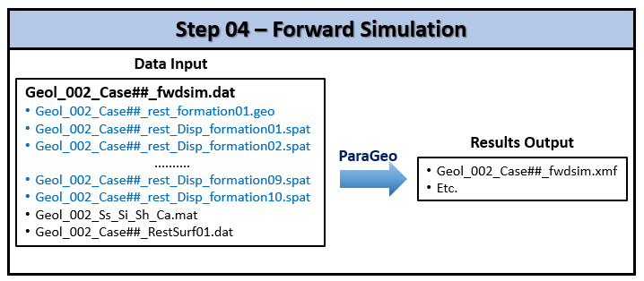
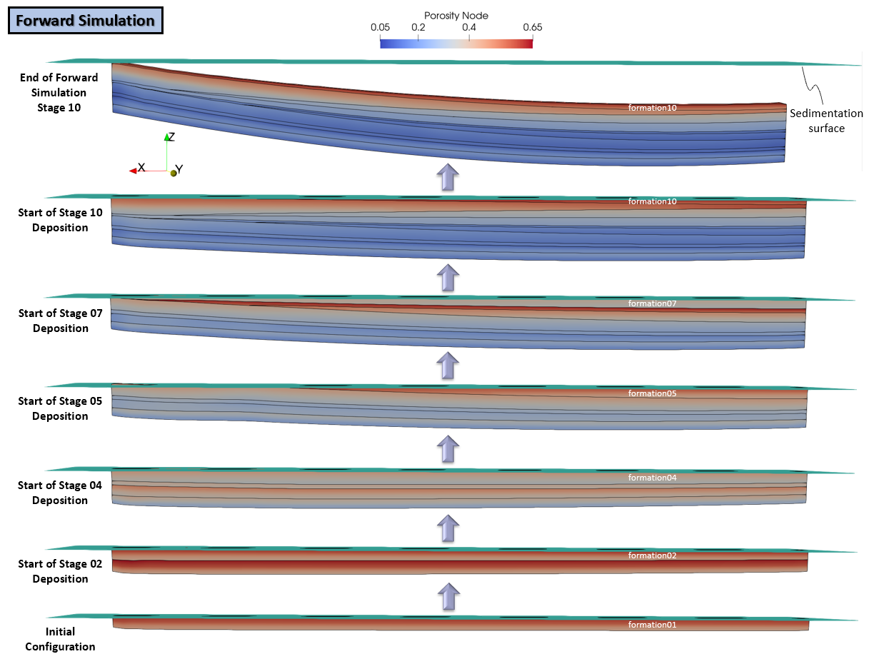
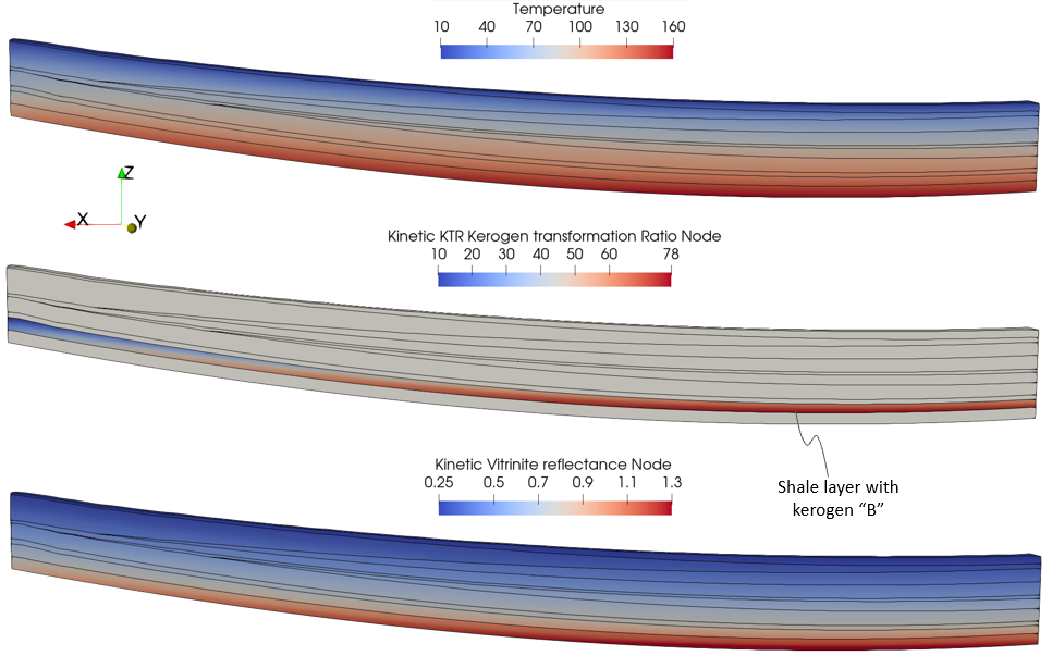
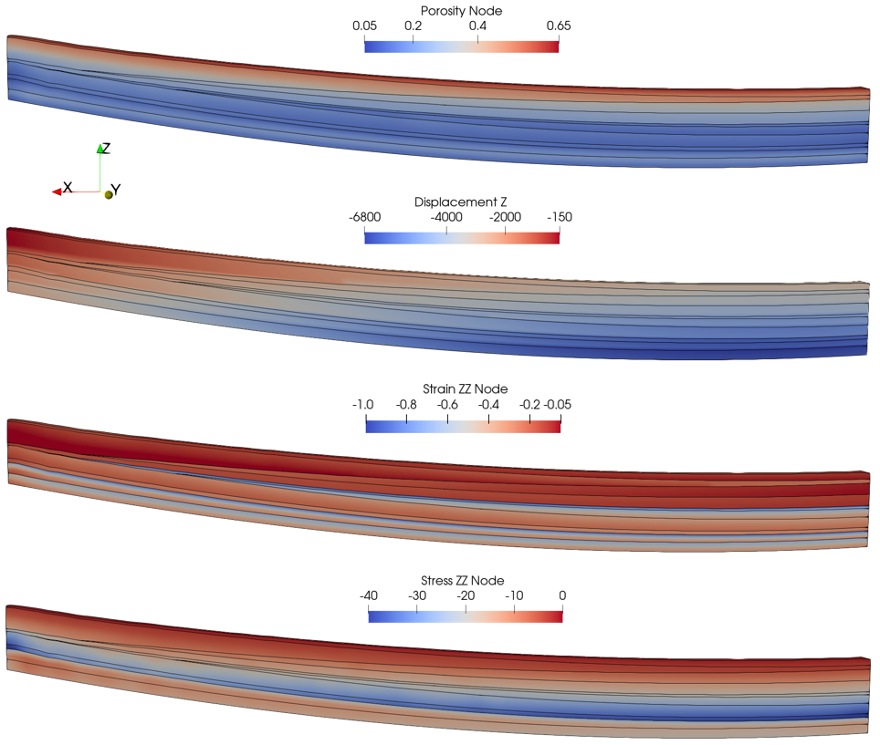
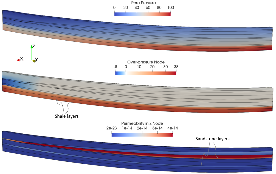
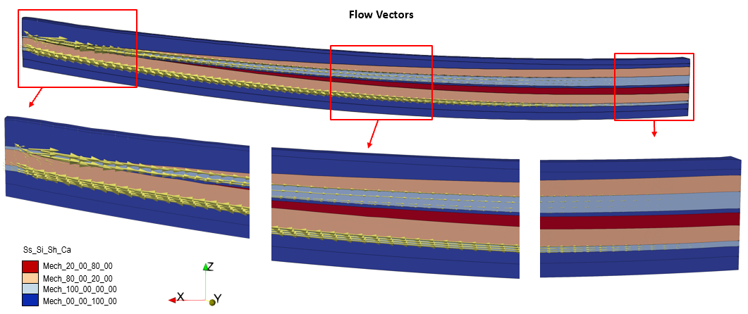
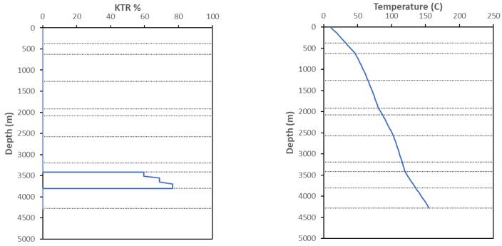
Step 04 involves performing the forward simulation for the slice model as shown in the flowchart below. The key files involved are the same as for the Case01 column model, likewise the simulation stages and process involved but with minor changes which are described in the next section.
The forward simulation data files for the slice model are in: Geol_002\Case02\04 - Forward simulation\Data.
Workflow Flowchart for Step 04 - Forward Simulation
Basic Set Up: Data File Description
|
|||||||||||||||||||||||||
|


