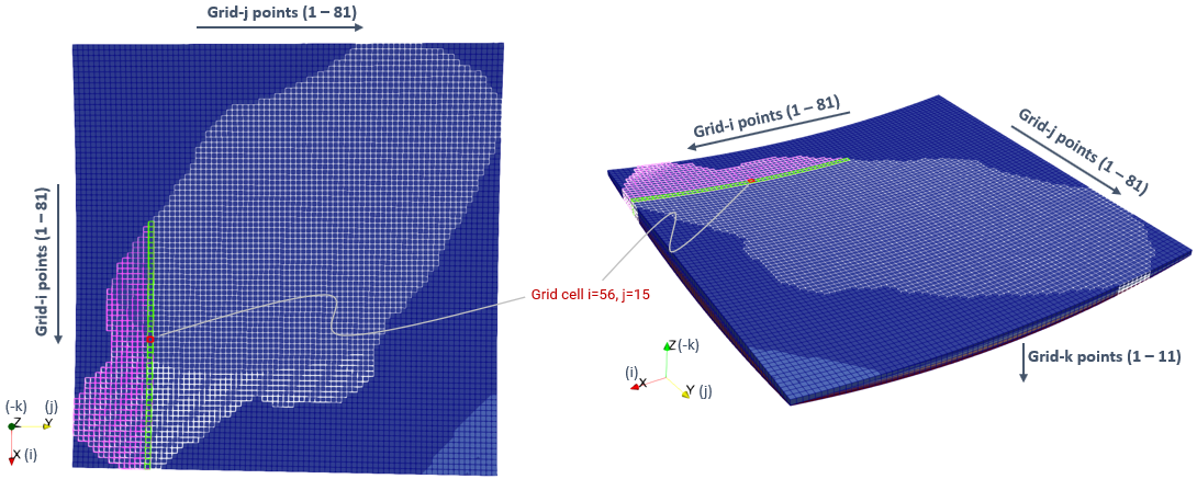
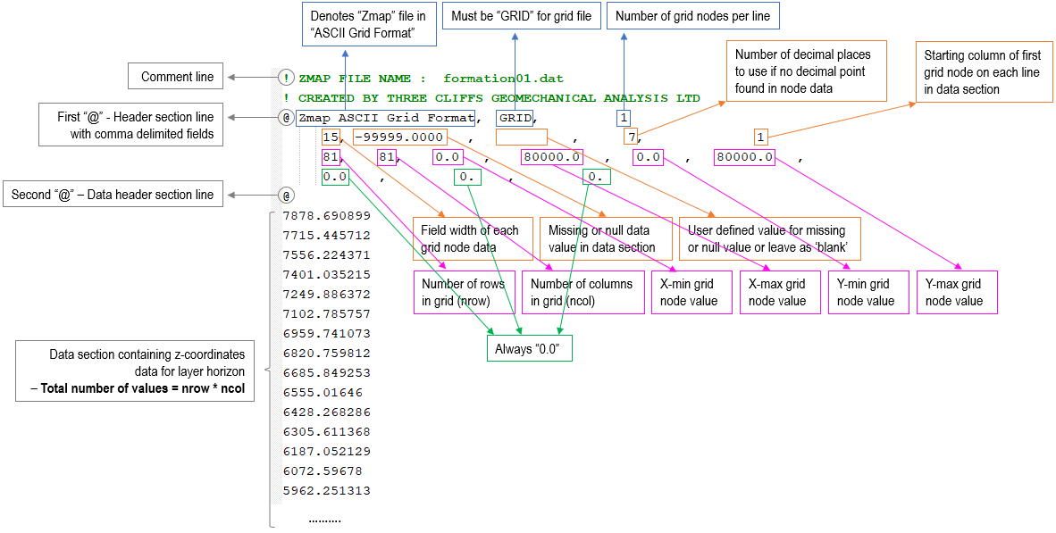
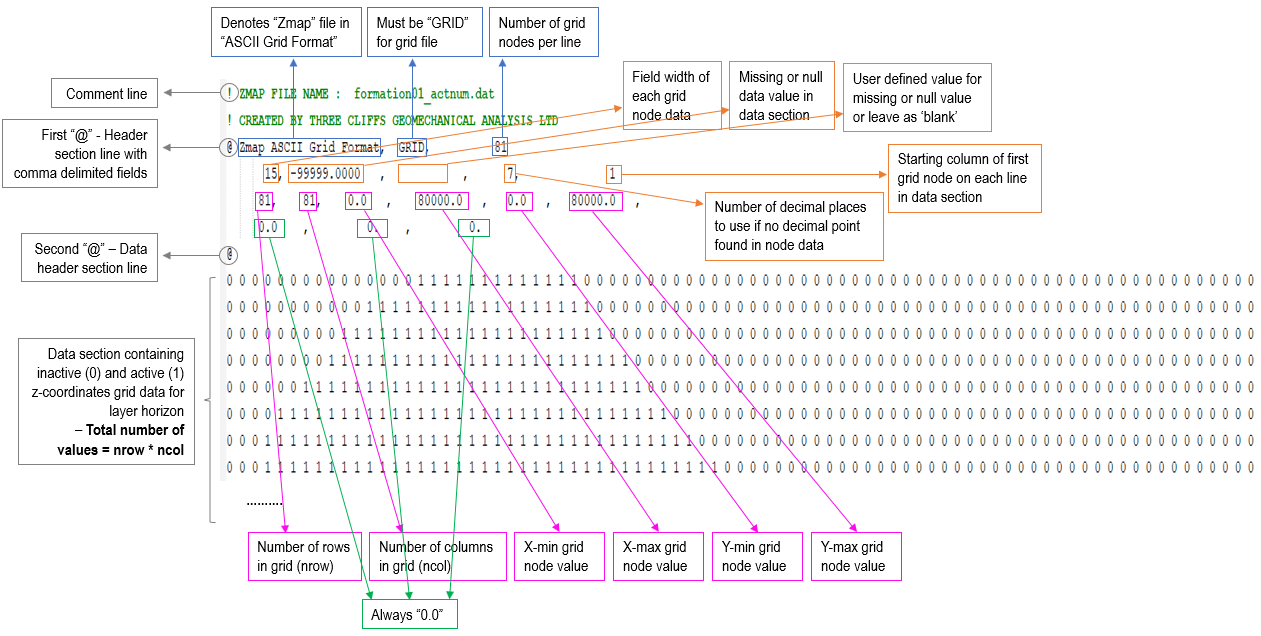
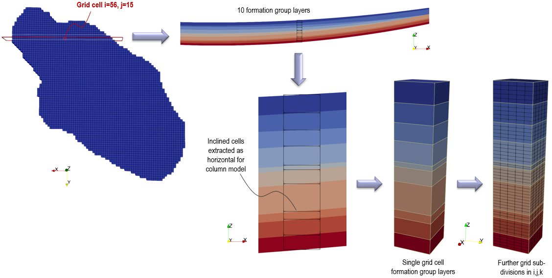
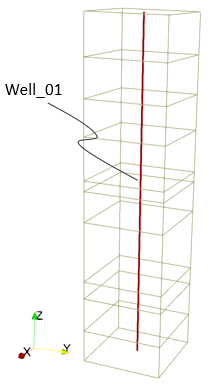
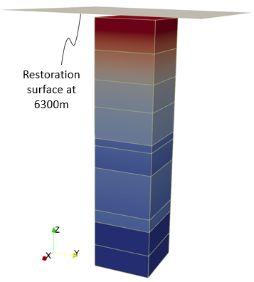
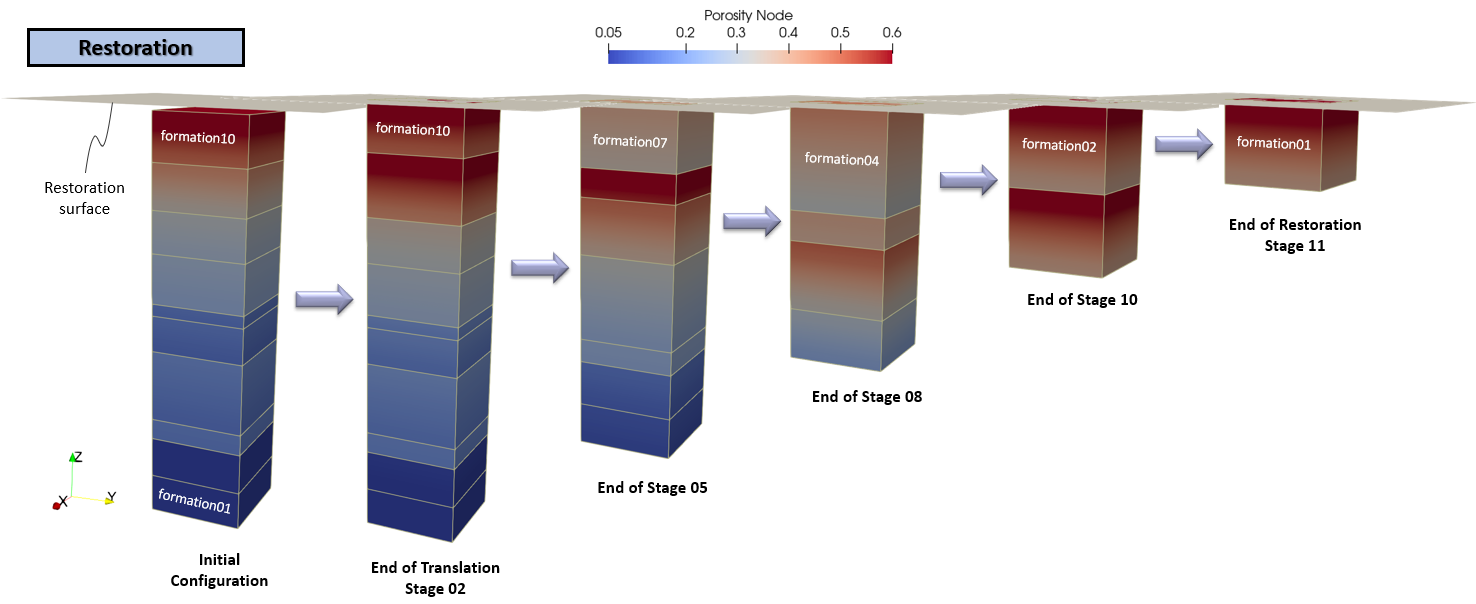
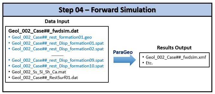
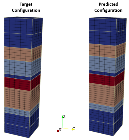
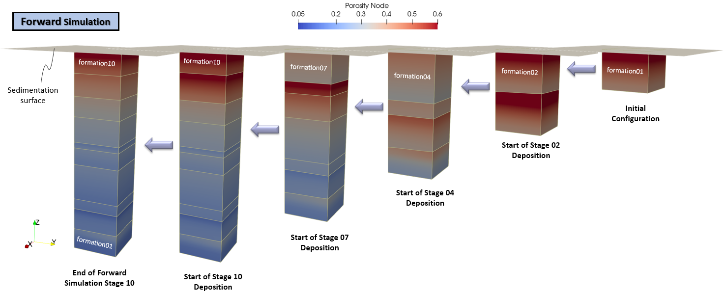
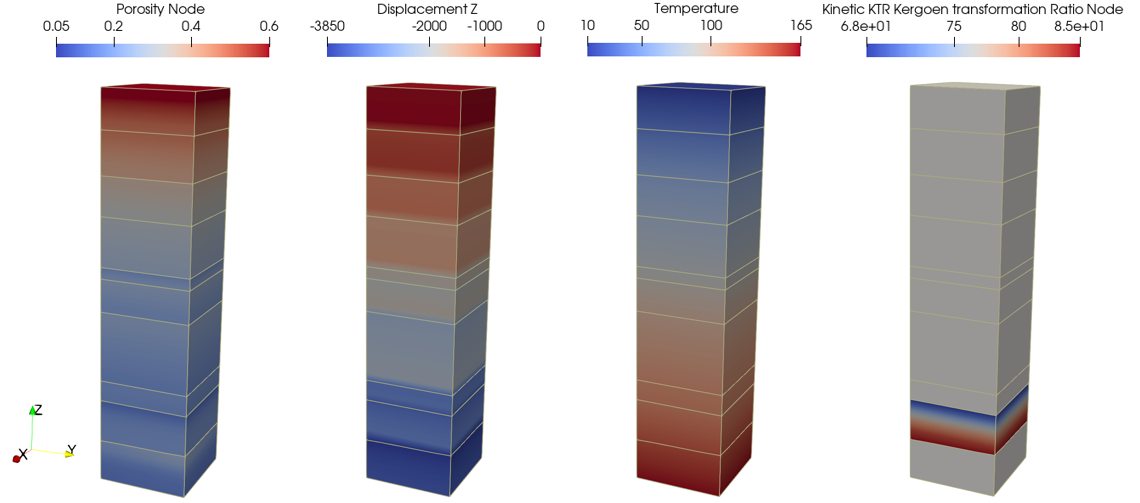
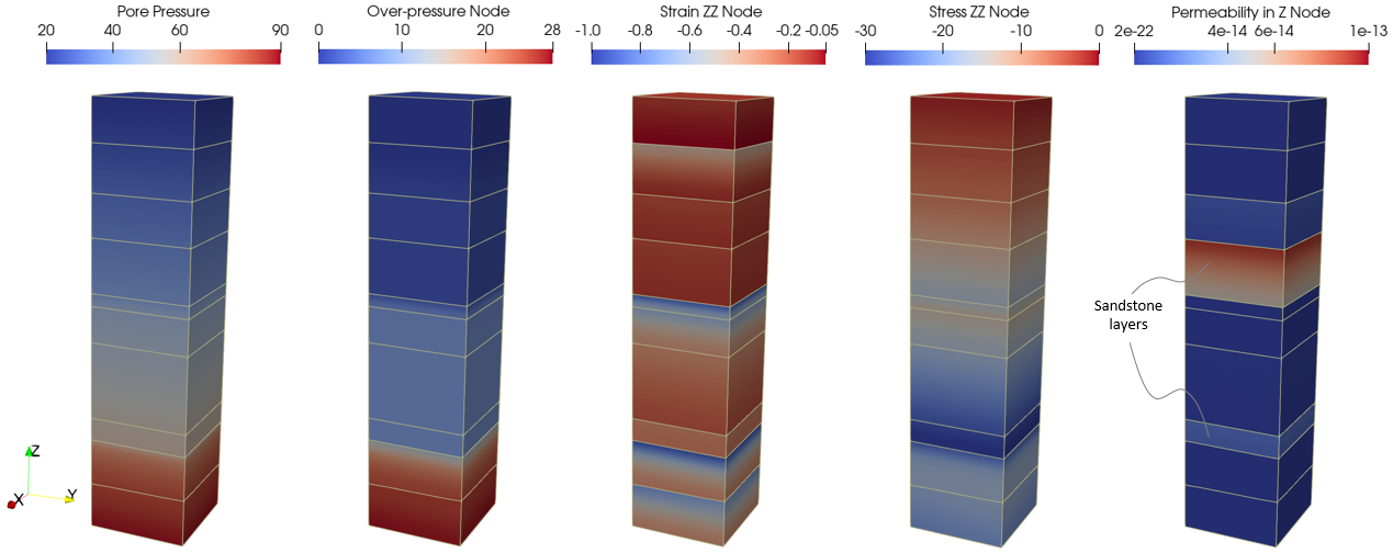
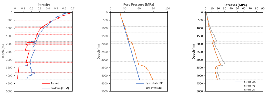
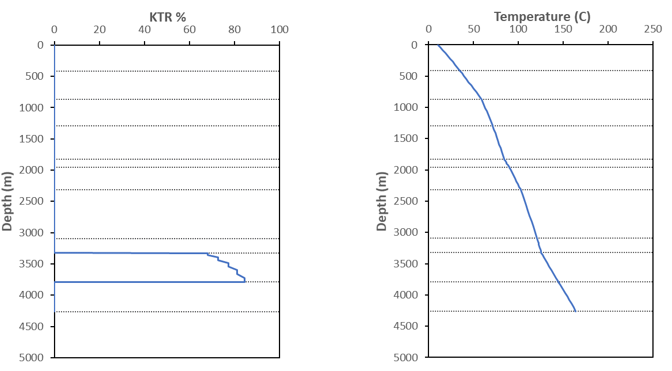
The basic data for the forward simulation includes:
1Geometry_data defining the external geometry .geo file with "hdf" file format to read in for the initial geometry for the forward model from Step 03 - restoration. 2Units defining length in "m", stress in "MPa", time in "Ma" and temperature in "Celsius". 3Hydrocarbon_kinetics defining the assignment and processing data associated with hydrocarbon kinetics, e.g. vitrinite maturation, oil -> gas cracking and hydrocarbon expulsion. 4Kerogen_kinetics defining the assignment and processing data associated with kerogen kinetics property name "kerogen1" for kerogen 'B'. 5Group_control_data activates geomechanical, seepage flow and thermal fields for the pre-existing group and Group_data defines the element type, material name, porous flow type, etc associated with the group. 6Material_data to read in the "Mech_00_00_100_00" material properties and the Fluid_properties contained in the external material file "Geol_002_Ss_Si_Sh_Ca.mat" for the pre-existing layer. This material file also contains all the other materials for the sedimentation layers. 7Stratigraphy_definition, Stratigraphy_horizon and Stratigraphy_surface_load defining stratigraphy data for the pre-existing layer. Stratigraphy_smoothing is deactivated and removed. 8Stratigraphy_basal_load defining the thermal flux loading of 1.766E+12 Nm/Ma/m2 (equivalent to 0.056 W/m2) on the base. 9Sedimentation_parameters, Sedimentation_horizon and Sedimentation_data defining the sedimentation data for the 9 new sediment layers over a duration of 3.0 Ma. 10Water_level_data defining a moving water level rising from 1000m to 2000m above the surface horizon of the model according to a defined time curve. 11Geostatic_data to define the initial stress state, prescribe an initial porosity vs depth trend via spatial data for the pre-existing layer and define the pore pressure distribution as hydrostatic using an s-curve time curve over 3.0 Ma. The porosity vs depth trend is the same as defined in Step 03 - restoration. 12Gravity_data to apply gravity load with an s-curve time curve over 3.0 Ma for the pre-existing layer. 13Support_data defining base fixed vertically and sides fixed horizontally. 14Spatial_boundary data defining the tracked displacements from restoration applied to the base and the sides of the forward model using a "Step_scurve" time curve over the stage duration. 15Damping_global_data defining the use of combined damping models (mass proportional damping of 0.02% and bulk viscosity damping with constant of 0.5) to aid the numerical stability of the model. 16Output_data defining the nodal data for output. 17History_section_line data for a notional Well_01 line path along the middle of the column to output variables such as temperature, pore pressure, hydrostatic pore pressure, porosity, stresses and Kinetic KTR at the end of every stage. The output will be in "las" format with 10 points per sedimentation layer. 18History_section_line data for a notional Well_01 line path along the middle of the column to output variables such as temperature, pore pressure, hydrostatic pore pressure, porosity, stresses and strains every 1.0 Ma. The output will be in "hdh" format with one point per sedimentation layer. 19History_global data to monitor various global energies every 1.0 Ma. 20Reference_set_data to output to the plot file change (from initial) in variables such as displacements, pore pressure, porosity, effective mean stress, deviatoric stress, stresses and strains. 21Couple_control_data to define an incremental coupling between the geomechanical, fluid flow and thermal fields using the variable group volume strain update algorithm based on undrained conditions. 22Porous_flow_control_data and Thermal_control_data are both defined using a "linear transient" solution algorithm 3. 23Control_data defining: (a) Incremental transient solution algorithm (Type 4), (b) Duration of 12.0 Ma, (c) Flow/Thermal time increment of 0.05 (i.e. coupling time step of 0.05 Ma, therefore 240 coupling times for stage duration of 12Ma. (d) Target number of mechanical steps per coupling step set to 100. (e) Plot file every 4.0 Ma (i.e. three plotfiles per stage). (f) Screen message output every 10 flow/thermal increments.
Following are descriptions of data defined in the data file, note that these may not be in the same order as they appear in the data file.
Data File
|
|
* Geometry_data
File_name Geol_002_Case01_rest_formation01.geo
File_format hdf
|
1Geometry_data defining the external geometry .geo file with "hdf" file format to read in for the initial model geometry for the forward model from Step 03 - restoration.
|
|
Data File
|
|
* Units
Length "m"
Stress "MPa"
Time "Ma"
Temperature "Celsius"
|
1Units defining length in "m", stress in "MPa", time in "Ma" and temperature in "Celsius".
|
|
•Defines the assignment and processing data associated with hydrocarbon kinetics, e.g. vitrinite maturation, oil -> gas cracking and hydrocarbon expulsion.
Data File
|
|
* Hydrocarbon_kinetics NUM=0
Maturation_model 'EasyRo'
Oil_gas_cracking_model GaussHI
Oil_gas_cracking_premult 0.1E15
Kerogen_gas_sorption 0.02
Kerogen_oil_sorption 0.10
Carbon_fraction_oil 0.85
Carbon_fraction_gas 0.85
|
1Maturation_model "EasyRo" is defined. 2Oil -> gas cracking model is defined as "GaussHI", i.e. Gaussian distribution dependent on the initial hydrocarbon index HI. This model has default properties for the activation energy constants a1 = 233.6 kJ/mol, b1 = 7.5 kJ/mol and variance constants a2 = 32.5, b2 = 8.55. 3The pre-multiplier A0 is defined as 0.1E15 Ma-1. 4Kerogen gas sorption coefficient aG is defined as 0.02 g/gC. 5Kerogen oil sorption coefficient aO is defined as 0.1 g/gC. 6Weight fraction of carbon in hydrocarbons in both oil and gas are set to 0.85 (i.e. 85%). |
|
•Defines the assignment and processing data associated with kerogen kinetics property name "kerogen1" for kerogen 'B'.
Data File
|
|
* Kerogen_kinetics NUM=1
Name "kerogen1"
Kerogen_facies_type "B"
TOC 20.0
Kerogen_density 1200
Hydrocarbon_density_model "Constant"
Hydrocarbon_density_properties IDM=1
865
|
1Kerogen property name "kerogen1" has the following parameters defined: 2Kerogen_facies_type is defined as organofacies 'B'. Default properties for kerogen 'B' are: Transformation index TI = 0.018, Hydrocarbon index HI = 0.592, Gas concentration ratio G = 0.17 and Weight fraction of carbon W = 0.75. 3TOC defines the total organic carbon by weight as 20.0 percent, i.e. 20% of the rock matrix mass is kerogen. 4Kerogen density is defined as 1200 kg/m3. 5The Hydrocarbon_density_model for the evaluation of the density of the expelled hydrocarbon is defined as "Constant". 6Hydrocarbon_density_properties define the density of the expelled hydrocarbon for kerogen 'B' as 865 kg/m3. This density is a combination of oil and liquid gas and is used for porosity update and pore pressure generation. |
|
Data File
|
|
* Group_control_data
Group_numbers IDM=1
10
Active_geomechanical_groups IDM=1
1
Active_porous_flow_groups IDM=1
1
Active_thermal_groups IDM=1
1
* Group_data NUM=10
Group_name "formation01"
Element_type "Hex8"
Material_name "Mech_00_00_100_00"
Porous_flow_type 4
Mech_Integration_type "Belytschko_elastic"
Mech_hourglass_properties IDM=1
1.0
Volumes IDM=1
10
Thermal_advection_flag 0
|
1Group_control_data defines the geomechanical, porous flow and thermal fields active for the pre-existing sediment group.
2Group_data defines data for the pre-existing group: a.Group_name is "formation01". b.Element_type is defined as "Hex8" for 8-node 3D hexahedral element. c.Material_name defines the name of the material assigned to the group as "Mech_00_00_100_00". d.Porous_flow_type is defined as 4 for coupled geomechanical/porous flow. e.Mech_integration_type is defined with the "Belytschko_elastic" hourglass control. f.In conjunction with the above, Mech_hourglass_properties for the factor of hourglass shear modulus to be used is defined with a value of 1.0. g.Volumes define the list of volumes making up the element group, in this case volume 10. h.Thermal_advection_flag is set to 0 to not include any thermal advection terms.
|
|
Data File
|
|
* Material_data
Material_name "Mech_00_00_100_00"
Material_file "Geol_002_Ss_Si_Sh_Ca.mat"
|
1The assigned "Mech_00_00_100_00" material is read in from the material file "Geol_002_Ss_Si_Sh_Ca.mat" .
|
|
The stratigraphy data associated with the pre-existing sediment comprise:
•Stratigraphy_definition - defines the unit name and basal horizon. For simplicity of stratigraphy data definition, the stratigraphy unit name and stratigraphy horizon name are defined with identical name to the Group_data name of "formation01". When this same naming convention is used, Horizon_numbers and Group_numbers are automatically set and need not be defined. •Stratigraphy_horizon - defines the top horizon geometry for the stratigraphy unit. •Stratigraphy_surface_load - define stratigraphy surface loading for mechanical stress, pore pressure and temperature.
Data File
|
|
* Stratigraphy_definition
Units IDM=1
"formation01"
Basal_horizon "Basal_surface"
* Stratigraphy_horizon NUM=1
Name "formation01"
Geometry_set "formation01_1"
* Stratigraphy_surface_load
Applied_stress 1.0
Time_curve_stress "Step_scurve"
Pore_pressure_flag 1
Temperature_flag 1
Temperature 10.0
Time_curve_temperature "Step_ramp"
* Stratigraphy_smoothing
Active_flag -1
* Stratigraphy_basal_load
Thermal_flux 1.766E+12
|
1Stratigraphy definition data: a.Stratigraphy unit name defined as "formation01" - same as the Group_data name. b.Basal horizon defined as geometry set named "Basal_surface".
2Stratigraphy horizon data for stratigraphy unit "formation01": a.Stratigraphy horizon name also defined as "formation01" for consistency. b.Top surface of unit is defined by geometry set named "formation01_1".
3Stratigraphy surface load defined with: a.Mechanical stress load of 1.0MPa applied to the top surface via a "Step_scurve" load curve. b.Prescribed temperature of 10 °C on the top surface via a "Step_ramp" load curve.
4Stratigraphy_smoothing defined to deactivate and remove any stratigraphy smoothing.
5Stratigraphy_basal_load defined with basal thermal flux load of 1.766E+12 Nm/Ma/m2 (equivalent to 0.056 W/m2).
|
|
Layer sedimentation is defined using three data structures:
1Sedimentation_parameters defining the data that is common to all sedimentation layers. This data structure is defined at the start before the first control stage. 2Sedimentation_horizon defining the moving target topology for the stratigraphy horizon of the new layers using a displacement time curve. This data structure is defined at the start before the first control stage. 3Sedimentation_data defining the stratigraphy unit name. This data structure is defined in each sedimentation stage with the new stratigraphy unit name for the deposited layer.
Sedimentation_parameters
•This data structure is defined at the start before the first control stage and contains data that is common to all sedimentation layers.
Data File
|
|
* Sedimentation_parameters
Sediment_horizon_name "Sed"
Minimum_thickness 40
Sedimentation_type "Structure"
Thermal_advection_flag 0
Couple_horizon_flag 1
|
1The target Sediment_horizon_name is "Sed". 2A minimum sediment thickness of 40m is defined. 3The sedimentation horizon type is "Structure" for hex elements. 4Thermal advection flag is set to 0 to not include any thermal advection terms. 5Couple_horizon_flag is set to 1 to apply couple freedoms to the tops of the deposited layer to remain horizontal. |
Sedimentation_horizon
•This data structure is defined at the start before the first control stage and defines a moving target topology for the stratigraphy horizon of the new layers using a displacement time curve. The target horizon is moving at a rate of 500m/7.5 Ma, therefore for the 15 new layers, the final horizon has displaced 7500m in 112.5Ma, i.e. total height of 8000m with initial height at the top of the pre-existing layer at 500m.
Data File
|
|
* Sedimentation_horizon NUM=1
Name "Sed"
Type "Facet"
Geometry_part "Restoration_surface"
* Include
Filename Geol_002_Case01_RestSurf01.dat
|
1The sediment horizon "Sed" is defined by the part geometry "Restoration_surface" read in from the external file "Geol_002_Case01_RestSurf01.dat". This is the same part geometry data used for the Step 03 - restoration.
|
Sedimentation_data
•This data structure is defined in each sedimentation stage and the only data to be changed are the stratigraphy unit name of the new deposited layer, the number of structured divisions in Z and Kerogen_assignment data for kerogen layers, which for this example, applies only to formation02.
Data File
|
|
* Sedimentation_data
Stratigraphy_unit_name "formation02"
Duration 3.0
Material_name "Mech_00_00_100_00"
Material_file "Geol_002_Ss_Si_Sh_Ca.mat"
Geostatic_set_name "Sedimentation"
Num_struct_divisions 5
Kerogen_assignment "kerogen1"
|
1The sedimentation data is defined in each sedimentation stage with data associated with the new deposited layer: a.Stratigraphy unit name. b.Material name. c.Number of structured divisions in the vertical direction - this is defined with the same number of divisions as in restoration. d.Kerogen_assignment data with the "kerogen1" property is defined only for formatio02 layer which has kerogen.
|
|
Data File
|
|
* Water_level_data NUM=1
Relative_level_flag 1
Reference_location IDM=2
55500
14500
Water_level_curve IDM=3 JDM=2
0 108 120
1000 1000 2000
|
1A moving water level is defined (Water_level_data) rising from 1000m to 2000m above the surface horizon of the model according to a defined time curve: a.Relative_level_flag set to 1 defines the water level to be relative to the surface horizon of the model at the Reference_location X and Y-coordinates specified. b.The rise in water level from 1000m to 2000m from 108 Ma to 120 Ma is defined by the Water_level_curve data.
|
|
Data File
|
|
* Geostatic_data NUM=1
Groups IDM=1
"formation01"
K_value_x 0.7
K_value_y 0.7
Porosity_spatial 1
Pore_pressure_distribution "Hydrostatic"
Time_curve 99
* Spatial_variation_definition NUM=1
! -------------------------------------
Description "Porosity vs. Depth"
Type "Absolute"
Distribution "Depth_dependent"
Variation_assignment 1
* Spatial_variation_values NUM=1
! ------------------------------------
Description "Mech_00_00_100_00"
Time 0.0
Values_vs_depth IDM=30 JDM=2
0 100 200 300 400 500 600 800 1000 1200
1400 1600 1800 2000 2500 3000 3500 4000 4500 5000
5500 6000 6500 7000 7500 8000 8500 9000 9500 10000
0.7000 0.6450 0.5945 0.5479 0.5051 0.4656 0.4293 0.3652 0.3109 0.2649
0.2259 0.1929 0.1649 0.1412 0.0966 0.0672 0.0478 0.0349 0.0265 0.0209
0.0172 0.0147 0.0131 0.0121 0.0114 0.0109 0.0106 0.0104 0.0103 0.0102
* Time_curve_data NUM=99
Name "Geos_init"
Time_curve IDM=2
0.0 3.0
Time_factor IDM=2
0.0 1.0
Curve_type 2
|
1Geostatic data is defined for the initialization of the pre-existing sediment group named "formation01" with hydrostatic pore pressure utilizing an S-curve time curve over 3.0 Ma.
2Also defined is the corresponding spatial data defining the initial porosity vs depth trend for the assigned material .
|
|
Data File
|
|
* Geostatic_data NUM=2
Name "Sedimentation"
K_value_x 0.7
K_value_y 0.7
Porosity_spatial #
Pore_pressure_distribution "Hydrostatic"
Time_curve 99
Deposition_flag 1
* Spatial_variation_definition NUM=#
! -------------------------------------
Description "Porosity vs. Depth"
Type "Absolute"
Distribution "Depth_dependent"
Variation_assignment #
* Spatial_variation_values NUM=#
! ------------------------------------
Description "Mech_##_##_##_##"
Time 0.0
Values_vs_depth IDM=30 JDM=2
.......
.......
|
1Geostatic data named "Sedimentation" is defined during the sedimentation stages for the initialization of the new deposited sediments with hydrostatic pore pressure utilizing an S-curve time curve over 3.0 Ma.
2Also defined is the corresponding spatial data defining the initial porosity vs depth trend for the assigned material .
3Note that the Time_curve 99 will automatically be scaled over the respective stage duration.
|
|
Data File
|
|
* Gravity_data
Gravity_constant 9.81
Time_curve 100
* Time_curve_data NUM=100
Name "Gravity"
Time_curve IDM=2
0.0 3.0
Time_factor IDM=2
0.0 1.0
Curve_type 2
|
1Gravity is defined with an s-curve time curve over 3.0 Ma for the pre-existing layer. |
|
Data File
|
|
* Support_data
Displacement_codes IDM=3 JDM=5
1 0 0
0 1 0
0 0 1
1 1 0
1 1 1
Displacement_code_geom_set IDM=5
"North"
"South"
"East"
"West"
"Basal_surface"
Displacement_code_geom_ass IDM=5
4 4 4 4 5
|
1The base of the model is constrained in all directions and the four sides, "East, "West", "North" and "South" are constrained in the two horizontal directions.
|
|
Data File
|
|
* Include
Filename Geol_002_Case01_rest_Disp_formation01.spat
* Spatial_boundary NUM=1 ! Basal displacements
Name "Base_condition"
File_name "Geol_002_Case01_rest_Disp_formation01.spat"
Boundary_type "Spatial_grid"
Time_curve "Step_scurve"
Conforming_mesh_flag 0
Spatial_grids IDM=1
"Disp"
Geometry_sets IDM=1
"Basal_surface"
Prescribed_components IDM=3 JDM=1
1 2 3
* Spatial_boundary NUM=2 ! North boundary displacements
Name "North"
File_name "Geol_002_Case01_rest_Disp_formation01.spat"
Boundary_type "Spatial_grid"
Time_curve "Step_scurve"
Conforming_mesh_flag 0
Spatial_grids IDM=1
"Disp"
Geometry_sets IDM=1
"North"
Prescribed_components IDM=2 JDM=1
1 2
(.........)
* Spatial_boundary NUM=5 ! West boundary displacements
Name "West"
File_name "Geol_002_Case01_rest_Disp_formation01.spat"
Boundary_type "Spatial_grid"
Time_curve "Step_scurve"
Conforming_mesh_flag 0
Spatial_grids IDM=1
"Disp"
Geometry_sets IDM=1
"West"
Prescribed_components IDM=2 JDM=1
1 2
|
1The spatial boundary .spat data file containing the tracked displacements from restoration is read in for the corresponding formation group in each stage and applied to the base and four sides "North", "South", "East" and "West" of the column model.
2One spatial boundary data set is required to prescribe the displacements for each geometry set, so a total of five sets are required per stage. a.Time_curve is "Step_scurve" defining the displacements to be applied over the stage duration. b.Conforming_mesh_flag is set to 0 for an arbitrary grid. c.Name of spatial grids is "Disp". d.Geometry_sets define the geometry component prescribed the displacements. e.Prescribed_components defines the list of prescribed displacements in the different directions for each spatial grid. Notes that these correspond to the Support_data constraints.
|
|
A combined damping model (mass proportional damping and bulk viscosity damping) is adopted to aid the numerical stability of model.
Data File
|
|
* Damping_global_data
Damping_models IDM=2
Percentage
Bulk
Percentage_damping 0.02
Bulk_damping_model "BulkViscosity"
Bulk_damping_properties IDM=1
0.5
|
1Damping_models define the damping models to be used in combination. 2Bulk viscosity damping with constant of 0.5 is utilized in combination with a small percentage damping of 0.02. |
|
Data File
|
|
* Output_data
Output_discrete_values 1
Output_average_values 1
Sedimentation_plot_flag 1
Nodal_output_flags IDM=7
1
1
0
0
1
1
1
|
1An Output_data data structure defining the nodal data for output (0 - no output, 1 - output) to plot files is specified. This can help to reduce the size of the results plot files. 2Additionally, discrete (non-averaged) element values and averaged element values are defined to be output (keywords set to 1). 3Sedimentation_plot_flag is set to 1 to define a plot file to be output after sedimentation of new material. Note that this functionality has now been superseded with the keyword definition Output_flag set to 1 in the Sedimentation_data data structure. |
|
Three different history data are defined in the first stage:
•History_section_line data set 1 to represent a notional Well_01 line path along the middle of the column to output variables in "las" format at the end of every stage - 10 points per sedimentation layer. •History_section_line data set 2 to represent a notional Well_01 line path along the middle of the column to output variables in "hdh" format at every 1.0 Ma - 1 point per sedimentation layer. •History_global data to monitor various global energies every 1.0 Ma.
Data File
|
|
* History_section_line NUM=1
Name "Well_01_las"
Output_frequency_increment -1
Point_distribution_type 0
Number_points 10
Section_type "Vertical"
Path_format 0
Formation_data_flag 1
Plan_coordinates IDM=2
55500 14500
Output_formats IDM=1
"las"
Element_data IDM=3
"Elt_temp" "Elt_pore" "Porosity"
Nodal_pore_pressure IDM=1
"Pore_nod"
Nodal_temperature IDM=1
"Temp_nod"
Hydrostatic_pressure_flag 1
Stresses IDM=3
"Strs_xx" "Strs_yy" "Strs_zz"
Hc_kinetics_state_variables IDM=1
"K_KTR"
* History_section_line NUM=2
Name "Well_01_hdh"
Output_frequency_time 1.0
Point_distribution_type 0
Number_points 1
Section_type "Vertical"
Path_format 0
Formation_data_flag 1
Plan_coordinates IDM=2
55500 14500
Output_formats IDM=1
"hdh"
Element_data IDM=3
"Elt_temp" "Elt_pore" "Porosity"
Nodal_pore_pressure IDM=1
"Pore_nod"
Nodal_temperature IDM=1
"Temp_nod"
Hydrostatic_pressure_flag 1
Strains IDM=6
"Strn_xx" "Strn_yy" "Strn_zz" "Strn_xy" "Strn_yz" "Strn_zx"
Stresses IDM=6
"Strs_xx" "Strs_yy" "Strs_zz" "Strs_xy" "Strs_yz" "Strs_zx"
* History_global
Output_frequency_time 1.0
Mech_global_energy_data IDM=7
"External" "Kinetic" "Elastic" "Inelastic" "Damping" "Bulk_visc" "Hourglass"
|
1History_section_line data set 1 is defined to represent a notional Well_01 line path along the middle of the column to output (in .las format) variables of the formation layers along the well path at the end of every stage: a.Name defines the .las output file name appended with "Well_01_las". b.Point_distribution_type set to 0 defines output at points based on Number_points. c.Number_points in conjunction with Section_type set to "Vertical" define the number of points to output to be 10 for each group/stratigraphy unit. d.Path_format is set to 0, i.e. vertical path. e.Formation_data_flag set to 1 defines the output of formation data for the section line based on vertical distance. f.Plan_coordinates defines the reference x- and y-coordinates for the section line in plan view to be located in the middle of the column. g.Output_formats data defines the output in "las" format. h.Element_data defines the list of element variables such as temperature, pore pressure, hydrostatic pore pressure, porosity, stresses and kinetic KTR for output.
2History_section_line data set 2 is similar to data set 1 but the output will be in "hdh" format with one point per sedimentation layer and output variables every 1.0Ma.
3History_global data is defined to output various global energies in the geomechanical field every 1.0 Ma.
|
Additional History_point data for Kerogen Layer (i.e. formation02 sediment)
Data File
|
|
* History_point NUM=1
Name "Kerogen"
Group 11
Output_frequency_time 1.0
Point_coordinates IDM=3 JDM=1
55500 14500 5600
Element_data IDM=3
"Porosity" "Elt_temp" "Elt_pore"
Hc_kinetics_state_variables IDM=13
K_CKO K_CKG K_CO K_CG K_CGO K_COE K_CGE K_CKI K_PI K_HI
K_VR K_KTR K_COTOT 2
|
1A History_point data is defined at a point in the kerogen layer formation02 sediment to output specified element variables and a list of hydrocarbon kinetics state variables every 1.0 Ma.
|
|
Data File
|
|
* Reference_set_data NUM=1
Name "Change"
Output_change 1
Groups IDM=1
"formation01"
Nodal_variables IDM=2
"Disp" "Pore_nod"
Element_variables IDM=10
"Porosity" "Effmean" "Vonmises"
"Strs_xx" "Strs_yy" "Strs_zz"
"Strn_xx" "Strn_yy" "Strn_zz" "Strn_xy"
Deposition_flag 2
|
1A Reference_set_data is defined in the first stage so that the change in the specified variables is output to the plot file. Because the data is named "Change", the output variables will be named according to the following format: e.g. "Change Delta Porosity". a.Deposition_flag set to 2 creates a reference set containing all active groups specified in set and newly deposited sediments. |
|
Couple Control Data
•Couple_control_data data structure defines the active fields (i.e. geomechanical, porous flow and thermal) for the analysis and additional data to control the coupling process. This is only required to be defined once before the first Control_data.
Data File
|
|
* Couple_control_data
Solution_algorithm "Incremental"
Volume_strain_coupling "Undrained"
Volume_update_model "VariableGroup"
Field_names IDM=3
"Geomechanical"
"Porous_flow"
"Thermal"
|
1Couple_control_data data structure defines the active fields (i.e. geomechanical, porous flow and thermal) for the analysis and additional data to control the coupling process. 2 An incremental staggered solution algorithm is defined. 3Volume_strain_coupling is set to "Undrained". 4Volume_update_model is set to "VariableGroup". |
Porous Flow and Thermal Control Data
•Porous_flow_control_data and Thermal_control_data define additional data to control the solution process. This is only required to be defined once before the first Control_data.
Data File
|
|
* Porous_flow_control_data
Solution_algorithm 3
* Thermal_control_data
Solution_algorithm 3
|
1 Both porous flow and thermal control data are defined using solution algorithm 3 for "linear transient".
|
Solution Control Data for Pre-existing Sediment and Sedimentation Layers
•The Control_data data structures here defines the coupled geomechanical/porous flow/thermal solution data for the stage. •The same Control_data is defined for the pre-existing sediment stage and sedimentation stages with only the Control_title changed for each stage.
Data File
|
|
* Control_data
Control_title "formation01"
Duration 12.0
Solution_algorithm 4
Initial_time_increment 0.05
Target_number_time_steps 100
Output_time_plotfile 4.0
Output_frequency_plotfile -1
Screen_message_frequency 10
Output_frequency_restart -1
|
1The key control data comprise: a.Solution_algorithm set to 4 (incremental transient algorithm) which allows more iterations in an increment if the solution is not converged. b.Initial_time_increment is set to 0.05, i.e. coupling time step of 0.05, therefore coupling frequency of 240 per stage. c.The Target_number_time_steps is set to 100, i.e. 100 mechanical steps per coupling step. |
|
|
