IX_002 Reservoir simulation
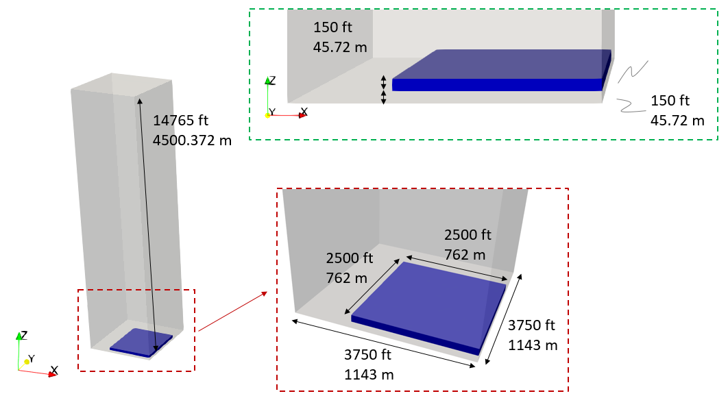
In this tutorial example a reservoir simulation coupling IX reservoir flow simulator and ParaGeo geomechanical capabilities will be undertaken. The model considers quarter symmetry. A producer well is located in the axis of symmetry whereas an injector well is located in the opposite corner of the reservoir. The ParaGeo model domain encompasses the reservoir, overburden, underburden and side burden, whereas the IX model domain considers only the reservoir. The ParaGeo model domain with its dimensions are shown in the figure below. The top surface of the reservoir is at 14765 ft depth (4500.372 m) has a thickens of 150 ft (45.72 m) and the underburden is also 150 ft. The half-length of the reservoir (because of the quarter symmetry) is 2500 ft (762 m). Half length of the considered domain is 3750 ft (1143 m).

Geometry and dimensions of the ParaGeo geometry. Reservoir is the blue volume, shale is the semitransparent grey volume
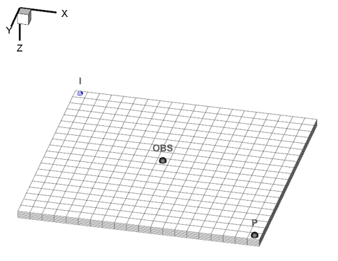
The IX mesh considers discretisation of the reservoir in 20x20x6 cells as shown in the figure below. There are three points located in the mesh: the injector (I), the producer (P) and an additional observation point (OBS).

IX mesh with injector (I), producer (P) and observation (OBS) points indicated.
The workflow for the ParaGeo-IX coupled simulations comprise the following steps:
1.ParaGeo geometry and ParaGeo reservoir mesh in IX format generation: In this step a ParaGeo .geo file containing the geometry, groups, mesh and geometry sets that will be considered for the simulation will be generated. A plot file for visualization in ParaView will also be output. Also a .bin mesh file for IX coupling will be generated. The mesh will only encompass the reservoir and the following considerations should be taking into account for conversion:
a.Required conversion of units (e.g. m to ft)
b.Application of any offset required so that the location of the reservoir coincides with that of the IX mesh (e.g. IX simulations often consider that the (x, y, z) = (0, 0, 0) is in the reservoir whereas in ParaGeo we might consider that it is in a point located in the overburden's top surface).
c.Change of reference coordinate system and rotation of the model. Note that Z coordinate in ParaGeo is positive upwards whereas IX adopts the Eclipse system in which Z coordinate is positive downwards.
2.Simulation run: The previously generated files will be used for the simulation.
Simulation Cases
SPSK_1 - Single porosity single permeability model with SR4 plasticity
SPSK_2 - Single porosity single permeability model (poroelasticity only)
DPDK_2 - Dual Porosity Dual Permeability model with a corridor of fractures
