DPDK_1 model
In this case a dual porosity dual permeability (DPDK) model will be considered (model with fractures). It is assumed that the user has already undertaken the SPSK example. The model domain and boundary conditions are identical to the previous case. Most material properties are also identical with the difference that a set of fractures is included in the reservoir. In this page the data used to include fractures in ParaGeo will be discussed.
Note that in this case any mechanical effect of fractures is neglected so that only the impact of fractures in the flow system is taken into account.
Definition of fractures
Data File |
|
* Material_data NUM=2 ! --------------------------------- Material_name "Reservoir" Grain_stiffness 30000E6 ! Pa
(...)
Singlephase_fluid 1 Fracture_set_names IDM=1 "fract_set1"
* Fracture_data NUM=1 ! --------------------------------- Name "fract_set1" Fracture_type "PreExist" Fracture_spacing 1.00 Coordinate_system_name "Fracture_Set1" Normal_stiffness_model "None" Normal_strength_model "None" Conductivity_model_name "PermPorosity" Conductivity_properties IDM=20 JDM=2 /"Porosity"/ 0.0001 0.0005 ... 0.05 /"Permeab."/ 7.48717E-05 0.009358958 ... 9358.957875 Initial_activation_flag 0
* Coordinate_system NUM=1 ! ---------------------------------- Name "Fracture_Set1" ! Rotation by +0 Degrees Direction_cosines IDM=3 JDM=3 1.000 0.000 0.000 0.000 1.000 0.000 0.000 0.000 1.000
|
1In Material_data fracture sets may be assigned by name using the Fracture_set_names keyword. The fracture set "fract_set1" is assigned to the reservoir.
2Fracture_data is the data structure which defines the properties for a fracture set. In this case a single set is considered which is named "fract_set1".
3Fracture_type is set to "PreExist". This model considers that fractures are already present in the reservoir before it is initialized (as opposed to fractures that may be propagated by hydraulic fracture mechanism for example).
4Fracture_spacing is used to define the distance between fractures (measured normal to the fracture plane). In this case is set to 1 m.
5Coordinate_system_name is used to define the coordinate system (which should be defined using the Coordinate_system data structure) that will define the orientation of the fractures in the fracture set.
6In the present example the fractures are not given mechanical properties and will only be relevant for the flow field. Hence both Normal_stiffness_model and Normal_strength_model are set to "None". Consequently it is assumed that the fracture porosity changes at the same rate that the matrix porosity (it will be updated using the same multiplier).
7The Conductivity_model_name is set to "PermPorosity" by which a porosity permeability function is provided in tabular form. It should be noted that the values provided are only used to calculate a permeability multiplier that will be passed to update IX fracture permeability (in the same manner as the matrix porosity-permeability; see the explanation in Material_data from SPSK_1) .
8Initial_activation_flag is set to 0.
9A Coordinate_system is defined to set the orientation of the fractures in the fracture set. The fracture plane orientation is perpendicular to the vertical component of the defined coordinate system. In this case the local fracture system coincides with the global coordinate system. Thus the defined set of fractures are horizontal.
|
Results
The result files for the project are in directory: IX_002\DPDK_1\Results
A case with horizontal fractures at every cell has been simulated. As stated above only the impact of fractures in the flow field is simulated (mechanical behaviour of fractures is not taken into account) .
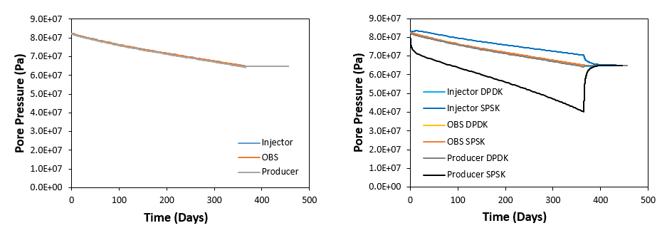
In the present case fractures act as flow conduits as permeability of fractures is high compared to matrix permeability. In the figure below it can be seen that the high permeability of fractures lead to almost perfect equilibrium of pore pressure in the reservoir thought the production history. When compared to results for SPSK case (figure on the right) it can bee seen that results at all well locations are very similar to the observation well location for the SPSK case which is located halfway between the injector and producer wells.
Evolution of pore pressure at the injector, observation and producer well locations (left) and comparison of pore pressure evolution at the three well locations with the SPSK case.
Evolution of stresses is shown on the figure below. It can be seen that:
1.As expected decrease in pore pressure during production results in an increase in effective stresses.
2.Evolution of stresses at the producer and observation well locations is very similar showing little differences in stress magnitudes.
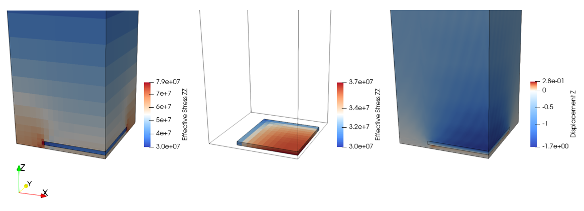
3.Stresses at the injector well location are lower than those at the producer and observation well locations even though the pore pressure magnitude is the same. This is because the producer well is located on the edge of the reservoir at the corner and the less compressible poroelastic surrounding shale holds part of the overburden stress. This can be seen in the effective stress contour plot below which shows an increase in vertical effective stress in the shale next to the reservoir.
4.Because of the equilibrium of pore pressure across the reservoir during production history and because the compaction in the reservoir is driven by the increase in effective stresses due to the overburden weight in all locations σ'z > σ'x = σ'y.
5.The larger stresses at producer and observation well locations lead to higher compaction and hence higher subsidence as shown in the displacement contours which show that vertical displacement in the overburden increases as we approach the producer well location.
Evolution of X, Y and Z effective stresses at the three well locations
Vertical effective stress and vertical displacement contours at the end of the simulation
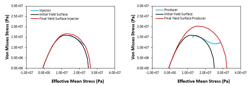
The stress paths in the p' - q space at injector and producer well locations is shown in the following picture. Note that the path for observation well location is not shown as is very similar to the path at producer well location. At both locations the path evolves initially with an increasing p' and decreasing q trend, moving towards the k0 path. At producer well location the larger stresses are reflected by a larger route of the stress path in which after reaching a minimum q value the path evolves with an increasing p' increasing q trend following the k0 path. As a result the yield surface size at the end of the simulation is larger (higher strength) at the producer well location than at the injector well location which is consistent with the corresponding amount of compaction experienced.
Stress paths in p'-q space at the injector (left) and producer (right) well locations
In the figure below evolution of porosity and permeability multipliers at the three well locations is shown. As mentioned above at producer and observation well locations there are larger stresses and larger compaction and subsidence. Thus the porosity and permeability at such locations decreases more rapidly than at injector well location.
Porosity and permeability multiplier evolution at the three well locations
In the same manner that matrix porosity and permeability in IX is updated using a multiplier calculated in ParaGeo, fracture properties are also updated. In the figure below evolution of fracture porosity and permeability multipliers and fracture porosity is shown for the three well locations. It can be seen that:
1.As mechanical properties of fractures are the same as for the matrix, fracture porosity evolution follows the same trend as matrix porosity evolution.
2.As fracture permeability is a function of fracture porosity, the evolution of permeability multiplier is consistent with that of fracture porosity.
3.As a result of the input fracture porosity - fracture permeability law, fracture permeability multipliers decrease more rapidly than fracture porosity multipliers.
Evolution of fracture properties at the three well locations
|


